

Content last revised on October 21, 2026
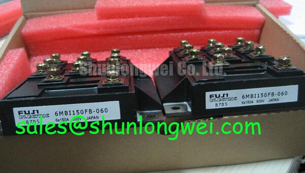
Fuji Electric 6MBI150FB-060: Product Identification and Repair Checks
- Isolate the DC link, verify discharge, and disconnect external current paths before comparing cold-state terminal resistance.
- Check the 6MBI150FB-060 marking against the equipment parts list and record the installed power-terminal and gate connections.
- Inspect the mounting surface, terminal hardware, and thermal interface for uneven contact, contamination, or mechanical damage.
- Check the gate-driver supply and fault-interlock wiring before authorizing a powered switching test.
The Fuji Electric 6MBI150FB-060 is a 600 V, 150 A IGBT module in a Fuji Power Module package. For a repair decision, these ratings establish the initial electrical match; terminal arrangement, drive compatibility, and thermal installation determine whether the module can be integrated into the existing assembly.
| Product identification | Specification | Parameter status |
|---|---|---|
| Model | 6MBI150FB-060 | Manufacturer part designation |
| Manufacturer | Fuji Electric | Product identity |
| Rated voltage | 600 V | Official Specification |
| Rated current | 150 A | Official Specification; operating conditions govern application |
| Package / case | Fuji Power Module | Specified package description |
| Detailed integration data | Terminal drawing, rating conditions, gate limits, thermal curves, and mounting requirements | Consult the exact manufacturer datasheet |
When evaluating electric material-handling equipment or forklift low-voltage traction controllers, compare the original circuit topology and switching requirements rather than assuming that a higher voltage rating establishes suitability. The 6MBI150FB-060 product reference identifies the procurement target; the equipment schematic remains the basis for connection and commissioning decisions.
Transient Dynamics & Electrical Design: Evaluating Thermal Capacitance and Heatsink Response on 6MBI150FB-060
Record the overload pulse duration, repetition pattern, and case-temperature trend before deciding whether a thermal trip originates in the module interface or the cooling assembly. A brief current surge and a sustained overload place different demands on the thermal path, even when the displayed peak current is similar.
Design Consideration: Junction temperature can rise substantially before the heatsink temperature changes noticeably. Thermal capacitance delays heat propagation through the assembly; it does not remove switching or conduction losses. A cool external heatsink immediately after a pulse therefore cannot establish a safe junction temperature.
For transient assessment, use the manufacturer’s junction-to-case transient thermal-impedance curve or a validated equivalent thermal network. An Engineering Calculation for an isolated constant-loss pulse uses the temperature rise expressed as ΔTj = P × Zth(j-c)(t), with measured case temperature providing the reference. This relationship assumes that the selected impedance curve and its boundary conditions represent the installation. Repetitive operation requires the accumulated response from preceding pulses, not just the response to the latest event.
A multi-RC model is useful when the load waveform contains several time scales. Fit its elements to the applicable thermal curve, feed it the estimated loss waveform, and compare the predicted junction peak with the documented temperature limit. Do not derive the network from package appearance or substitute steady-state thermal resistance for a short-pulse response. The model supports a margin assessment only when its loss inputs and boundary temperatures are credible.
At the bench, inspect contact uniformity before changing cooling hardware. Residue, a distorted mounting surface, or uneven fastening can interrupt the intended heat path. Apply the specified interface material and fastening procedure, then repeat the same operating sequence with temperature measurements taken at consistent locations. A changed case-to-heatsink temperature difference is useful evidence, but it should be interpreted alongside airflow, coolant conditions, and load history.
Keep clearance around live terminals and measurement attachments consistent with the equipment’s insulation design. Probe fixtures and temporary temperature sensors must not bridge the separation built into the assembly. This preserves the test arrangement without assigning an unsupported clearance dimension to the module.
6MBI150FB-060 Thermal-Electrical Optimization: Gate Driver Auxiliary Power Sequencing
Capture the driver auxiliary rails, gate-emitter waveform, enable signal, and fault output during startup and shutdown before reconnecting the full operating load. The useful question is whether the driver maintains a defined gate state throughout each transition, including supply collapse and fault recovery.
Design Consideration: Coordinate auxiliary-power readiness, undervoltage lockout, and switching permission so that the power stage cannot receive uncontrolled commands while the driver supply is unsettled. Where the approved circuit uses negative turn-off bias, verify that this rail reaches its intended operating condition before switching is enabled. Its magnitude must come from the module limits and driver design, not from a generic negative-bias prescription.
Measure gate voltage relative to the appropriate emitter reference using a suitably rated differential measurement arrangement. A waveform referenced to controller ground can conceal local emitter movement or exaggerate gate disturbance. Compare startup, normal switching, and fault shutdown separately; a stable running waveform does not prove that the power-up sequence is controlled.
If the existing driver uses a bootstrap supply, examine its charging opportunities over the actual command pattern. Long intervals without recharge can change the available driver voltage. Capacitor charge balance, driver consumption, leakage, and charging-diode behavior belong in that assessment. Select any corrective component values from the driver requirements and measured operating envelope rather than assigning a universal bootstrap capacitance.
For equipment containing parallel modules, compare branch currents while also checking gate timing, connection resistance, and cooling symmetry. A positive temperature coefficient of saturation voltage can assist static sharing only within the operating region where that behavior is documented. It is not an established sharing guarantee for this part, and it does not resolve dynamic imbalance caused by unequal gate or power-loop inductance.
Use comparable busbar paths and driver-return geometry to reduce asymmetry, then evaluate branch waveforms under the intended conditions. The 2MBI150NC-060-10 provides a related comparison reference, not an automatic replacement: circuit configuration, terminal mapping, switching characteristics, and mounting compatibility remain separate checks.
6MBI150FB-060 Circuit Protection & Reliability: Evaluating Antiparallel Freewheeling Diode Reverse Recovery
Locate the inductive-current commutation path on the equipment schematic before attributing a turn-on current spike to the IGBT. Where the circuit uses an antiparallel freewheeling diode, its reverse-recovery current can contribute to the measured switch current as conduction transfers between branches.
Design Consideration: Evaluate recovery peak, recovery-current slope, collector-voltage overshoot, and ringing together. A sharp recovery transition can excite the parasitic inductance and capacitance of the commutation loop. The observed waveform depends on diode behavior, operating temperature, load current, switching speed, and the physical layout; a single spike does not identify one failed component.
Use controlled switching measurements with appropriately rated probes and current sensing. Establish whether the apparent ringing changes when probe placement changes before modifying the circuit. Measurement-loop pickup can resemble a power-stage disturbance, particularly near high-current connections.
If the measurements justify adjustment, evaluate turn-on gate damping and snubber behavior as a coupled trade-off. Slower turn-on can reduce commutation stress while increasing switching loss. A snubber can absorb oscillatory energy while introducing its own dissipation and pulse-loading requirements. Component selection should follow measured waveforms, permitted losses, and the equipment’s switching conditions, rather than a fixed resistor-capacitor recipe.
For circuits that return energy to the DC link, examine the braking path separately from freewheeling commutation. Fuji Electric’s Brake Chopper IGBT Modules reference describes that distinct product category; it does not establish brake-chopper functionality for the 6MBI150FB-060. In equipment using resistor braking, chopper control and resistor energy capacity require their own system-level assessment.
Likewise, the 6MBI30FA-060 is a separate IGBT-module reference when reviewing a companion switching or auxiliary power stage, not evidence of a front-end rectifier function. Identify each device’s actual role from the schematic before comparing it with the installed assembly.
For broader explanation of gate-loop interaction, thermal paths, and switching topology, the distributor’s IGBT Design & Integration guide provides supporting context. Keep the repair acceptance criteria tied to this module’s documentation and the equipment’s measured behavior.
Assembly Integrity & Layout Architecture: Auxiliary Kelvin Emitter vs Main Power Emitter Connections for 6MBI150FB-060
Trace the driver return from the board connector to the module terminal drawing before moving any emitter connection. A low-current driver reference and a load-current emitter path serve different purposes, but a dedicated auxiliary Kelvin emitter must not be assumed from package appearance or terminal position.
Design Consideration: Shared emitter-path inductance develops a voltage during rapid load-current changes. That voltage alters the effective gate-emitter drive and can contribute to unintended switching disturbance. Where the documented terminal arrangement provides a separate driver reference, route the gate and its return as a compact pair, keeping the return out of the load-current path.
If the installation has no documented auxiliary emitter connection, do not create one by attaching the driver return to an arbitrary nearby conductor. Preserve the approved connection arrangement and assess the shared-path effects through the actual circuit geometry. Shortening a wire is not automatically beneficial if it changes the reference point or reduces required electrical separation.
During reassembly, check that the busbars seat without forcing the module terminals sideways. Confirm that control connectors are fully engaged and that cable routing does not place the gate loop beside a high-current commutation loop unnecessarily. Follow the specified mounting sequence and inspect the thermal interface for even coverage.
Field Alert: Verify DC-link discharge before touching terminals, and use the specified fastening procedure rather than tightening by feel.
On the first controlled restart, compare the gate-emitter waveform at the module with the driver output, using equivalent measurement references. Differences can help locate connection inductance, coupling, or return-path disturbance. If an unexpected gate excursion remains, inspect the return routing and interlock behavior before increasing load; accept the repaired assembly only after its switching waveforms and thermal response satisfy the equipment’s documented test requirements.