

Content last revised on October 4, 2026
Benchtop Waveform Tuning and Voltage Margin for 6MBI15S-120-02
With the drive isolated and the DC link discharged, compare cold terminal measurements on the 6MBI15S-120-02 against the equipment schematic before reconnecting the gate driver. A reading taken without identifying the terminals can confuse an antiparallel diode path with a fault. Record the measurement polarity and compare each equivalent circuit position rather than relying on a single resistance value.
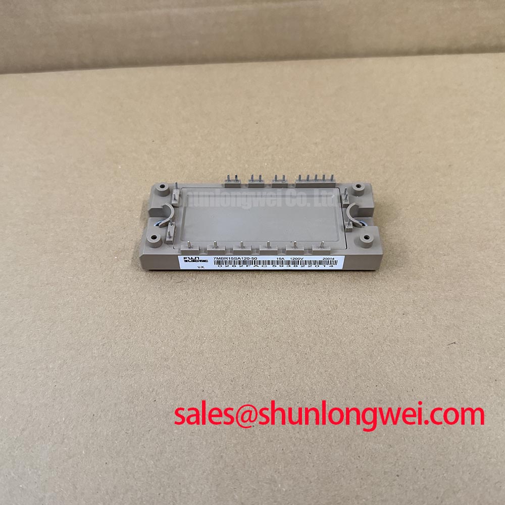
The Fuji Electric 6MBI15S-120-02 is listed as an IGBT module with a 15.0 A rated current and a 20.0 V voltage entry in the supplied product parameters. The voltage entry does not identify its terminals or rating conditions. Do not treat 20.0 V as the collector-emitter blocking rating. Obtain the exact manufacturer datasheet and confirm the voltage designation, current test conditions, terminal diagram, and mechanical drawing before assessing a repair or replacement.
Begin a voltage-margin assessment at the installed drive, not at the part number alone. Check the documented DC-link operating range, braking events, and measured collector-emitter waveform at turn-off. As a Design Consideration, the relevant margin is between the highest measured transient and the manufacturer-confirmed blocking limit under the applicable operating conditions. The supplied 20.0 V entry cannot establish that limit.
Altitude and terrestrial radiation can matter to power-semiconductor reliability, but no model-specific cosmic-ray, single-event burnout, or failure-in-time data is available in the supplied parameters. A quantitative derating or lifetime claim would therefore be unsupported. For equipment exposed to unusual environmental conditions, engineers can use the broader Industrial Applications discussion to frame questions for the system qualification plan, while obtaining applicable limits from the manufacturer’s documentation.
When tracing a suspected switching fault, inspect the gate command, DC-link voltage, and collector-emitter response on the same event. A transient that changes with load or braking demand may point toward the surrounding circuit; it does not, by itself, establish a module defect. Keep probe connections short and use measurement equipment appropriate to the circuit’s potential.
DC-Link Layout and Thermal-Electrical Checks
Inspect the physical path from the DC-link capacitor bank through the module and back to the capacitor terminals. As a Design Consideration, minimizing that loop’s parasitic inductance helps restrain turn-off overshoot. Capacitor placement, conductor geometry, and a symmetrical busbar arrangement should be evaluated together, then verified by switching measurements in the actual assembly. The final snubber choice and allowable peak voltage are system-level decisions, not specifications supplied for this module.
Pro Tip: Keep the outgoing and return current paths closely coupled, then verify turn-off peak voltage with a properly rated differential measurement during controlled switching tests.
Thermal inspection should follow the same circuit path. Review the heatsink contact, mounting condition, airflow, and temperature-sensing location before attributing a hot running position solely to the semiconductor. Compare temperatures under repeatable load conditions and check the manufacturer’s mounting instructions before changing hardware or assembly practice.
In a drive architecture review, the 6MBI100L-060 can be examined as a separate module within a broader power-stage comparison; its role and electrical compatibility cannot be inferred from the related model name. Fuji Electric’s information on RC-IGBT modules describes another product family and should not be used as a substitute for the 6MBI15S-120-02 datasheet.
Protection, Current Balance, and Replacement Assessment
For a failed-position investigation, review the schematic for desaturation sensing, gate-supply supervision, and the controller’s response to a fault signal. Check whether the driver reports a fault before, during, or after the abnormal current waveform. These observations help separate a protection-path problem from an event originating in the power stage, although neither is conclusive without further testing.
Do not assume that the 6MBI15S-120-02 has a particular temperature coefficient or will share current satisfactorily with another module. Those questions require the applicable output-characteristic curves and system measurements. If parallel devices are present, symmetrical power paths and matched gate-loop geometry are Design Considerations for dynamic balance; actual sharing must be checked across the equipment’s operating range.
For procurement comparison, the 6MBI15L-060 is a related model worth placing on a specification checklist, not an established drop-in replacement. Compare the manufacturer-confirmed terminal layout, blocking rating, current conditions, gate requirements, thermal characteristics, and mounting dimensions before considering interchangeability. A multi-joint robotic articulator drive is one possible equipment context for that assessment, subject to its own inverter and protection requirements.
Hard-Switching Faults and Controlled Turn-Off
Capture the gate-emitter and collector-emitter waveforms around a protection event while following the equipment manufacturer’s safe test procedure. An apparent short-circuit event may involve the load, bridge timing, driver supply, or sensing circuit. Compare the fault signal with the switching command and the measured current path before changing protection settings.
As a Design Consideration, a protection circuit may need to detect an abnormal current condition promptly while limiting the overvoltage produced when that current is interrupted. Detection timing and any staged turn-off behavior must be set from the exact module’s short-circuit operating limits and validated in the installed circuit; no short-circuit withstand time is established by the supplied product parameters. Fuji Electric’s brake chopper IGBT module information provides context for a distinct switching function, not a protection rating for this part.
If a bench test shows excessive turn-off ringing, review the gate-loop routing, DC-link return path, and voltage-probe setup before changing components. Repeat the measurement under controlled conditions after each adjustment, and judge the resulting peak voltage against the correctly identified manufacturer limit.