Content last revised on October 26, 2026
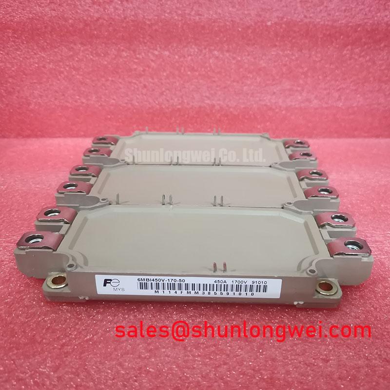
6MBI450V-170-54 Fuji Electric 1700V 450A IGBT Module
When a converter cabinet reports abnormal phase-current heating, isolate the DC link, allow the discharge circuit to complete, verify the absence of hazardous voltage using the approved safety procedure, and inspect the module terminals, busbar joints, and heatsink contact before applying any further switching pulses. The 6MBI450V-170-54 is a Fuji Electric IGBT power module in the 1700 V, 450 A class. These are device ratings, not recommended continuous operating conditions.
These ratings identify the component class for high-power conversion work, but they do not replace the switching, thermal, gate-drive, insulation, and protection limits established by the complete converter design. Engineers evaluating this part for a multi-megawatt offshore or onshore wind turbine full-scale converter should compare the original topology, cooling arrangement, gate-driver interface, busbar geometry, and protection timing before approving a replacement.
Field Diagnostics and Commissioning for Terminal Contact Stability
Terminal contact resistance should be audited before full-load commissioning because a bolted joint can create local heating even when the semiconductor junction remains within its expected electrical condition. Use a calibrated micro-ohmmeter with a four-wire connection across the assembled joint, keeping the probe placement consistent between phases and between commissioning visits. Acceptance criteria should come from the approved connection design or equipment service procedure, rather than being treated as an official electrical specification of the IGBT module itself.
Record the condition of the busbar, terminal surface, washers, fasteners, and mating faces before tightening. Oxidation, uneven seating, damaged plating, trapped debris, or a busbar that pulls sideways on the terminal can produce an unstable measurement. A single resistance reading is less useful than a comparison made under repeatable probe pressure and identical temperature conditions. If the measurement changes materially after mechanical rework, repeat the inspection rather than treating the first value as a permanent baseline.
Thermographic inspection should follow a controlled current ramp. Compare corresponding phase terminals, busbar transitions, and heatsink regions while the converter operates at a documented load point. A warmer terminal region may indicate joint resistance, uneven current distribution, airflow restriction, or an adjacent connection problem; confirm the electrical and mechanical path before assigning one cause. The thermal image should be stored with cabinet temperature, load condition, fan status, and measurement location.
For wind turbine converter cabinets, the layout should preserve clear access for torque-tool engagement, infrared inspection, and future cleaning. Busbars should enter the module without imposing bending force on the terminal stack. The complete current path must be reviewed for symmetry, especially where parallel module positions share a DC link or phase leg. Designers should also assess creepage, clearance, vibration restraint, and enclosure condensation controls according to the equipment insulation design and applicable installation requirements.
Maintenance Note: Inspect heatsink cleanliness, thermal-interface material condition, airflow balance, and terminal temperature trends during scheduled service rather than waiting for a converter trip.
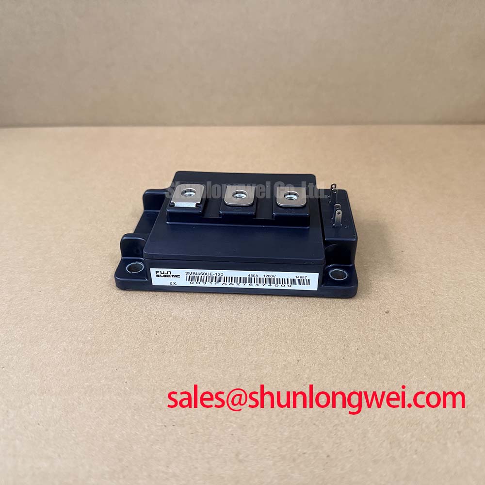
The 6MBI450V-170-54 belongs in a replacement assessment only after the original module’s electrical arrangement and mechanical footprint have been matched. A different Fuji Electric module, such as 2MBI100U4H-170, may be reviewed as a separate engineering candidate, but its rating, terminal arrangement, thermal path, and gate-drive behavior must be assessed independently rather than assumed interchangeable.
Circuit Protection and Oscilloscope Verification of Gate Switching
When a modern IGBT module is connected to a legacy drive board, the external turn-on and turn-off gate-resistor paths should be checked as part of the commissioning record. The purpose of separate RG(on) and RG(off) paths is to control the two switching transitions independently. A resistor value that worked with an earlier module can produce a different switching waveform after a module change because gate charge, internal capacitance, driver output impedance, and commutation conditions are not identical.
Use appropriately rated isolated or differential voltage probes and a suitable current probe to observe gate-to-emitter voltage, collector-emitter voltage, and phase current during controlled low-energy tests. Look for excessive ringing, a slow gate plateau, unexpected Miller coupling, or a turn-off transition that drives the collector-emitter voltage close to the module’s rated boundary. The adjustment objective is not simply the fastest edge. It is a controlled compromise between switching loss, voltage overshoot, electromagnetic disturbance, and thermal loading.
Any change to gate resistance should be validated across the operating temperature and load range relevant to the converter. The final value is system-determined and should be selected from the measured waveform, driver capability, protection timing, and thermal results. The module rating of 1700.0 V is an official device parameter; it is not a permission to operate a DC link at that level without verifying transient headroom and insulation coordination.
Parallel modules require particular attention to static and dynamic current sharing. IGBT saturation voltage generally has a positive temperature coefficient in the relevant operating region, which can support balancing under suitable conditions, but it does not remove the need for matched thermal paths and symmetrical busbar geometry. Keep the power loop and gate-drive loop physically consistent between parallel positions. Differences in emitter inductance, gate-loop length, or cooling can cause one position to switch or heat differently from the others.
Dead-time settings should prevent simultaneous conduction of opposing devices in the same bridge leg, while avoiding unnecessary diode conduction and reverse-recovery stress. The correct interval depends on the driver propagation delay, module switching behavior, load current, temperature, and commutation path. Confirm the result with oscilloscope captures at the actual driver terminals, not only at the controller output. Fuji Electric’s information on brake chopper IGBT modules provides useful manufacturer context for high-power braking applications, while the applicable device data must still be matched to this specific model.
Transient Dynamics, DC-Link Margin, and High-Altitude Assessment
Transient evaluation should begin with the measured collector-emitter waveform at the module terminals, because the installed busbar and commutation loop determine the voltage seen during turn-off. Stray inductance converts rapid current change into an additional voltage excursion, so the test setup should place the voltage probe close to the power terminals and use a short, properly compensated connection. The result should be compared with the DC-link operating condition, switching temperature, and protection threshold.
For a wind turbine full-scale converter installed at elevation, engineers may also assess terrestrial neutron exposure and the potential for single-event burnout. This is a reliability study rather than a rating that can be inferred from the 1700.0 V nameplate value. A defensible FIT or SEB assessment requires a qualified radiation environment model, device-specific qualification data, applied-voltage distribution, mission profile, altitude, shielding, and failure criteria. Without those inputs, a numerical failure rate, lifetime prediction, or altitude derating factor cannot be established for this module.
The practical commissioning task is to establish the actual DC-link voltage range, overshoot distribution, fault-clearing response, and repetitive thermal load. Capture turn-off events at representative current levels and include regenerative conditions from the turbine-side converter. If a braking chopper is used to absorb regenerated energy, verify the chopper command, resistor bank response, and DC-link clamp behavior as one protection chain. The switching waveform should remain inside the validated system boundary under normal operation and controlled fault tests.
Designers should minimize parasitic power-loop inductance to reduce turn-off overshoot, then verify peak voltage against the system’s insulation and semiconductor margins. Snubber selection, clamp placement, capacitor connection, and busbar layering are system decisions. The practical relationships between commutation geometry, transient control, and snubber design are discussed in Mastering Power System Dynamics. That engineering reference should complement, not replace, the module documentation and converter-level test plan.
Use a fault recorder to correlate gate command, gate voltage, collector-emitter voltage, phase current, DC-link voltage, and protection action. An isolated waveform that appears acceptable can still conceal a timing problem between current detection and gate blocking. Review the captured event with the driver interlock state and temperature data so that transient behavior is evaluated as part of the complete protection sequence.
Assembly Integrity and Floating Gate-Bias Supply Sequencing
Floating gate-driver supplies should reach their valid operating state before the high-voltage DC link is connected. The power-up sequence should confirm auxiliary supply stability, driver enable status, undervoltage lockout behavior, and a defined gate-off condition. If the original driver architecture specifies a negative turn-off bias, the system integrator must verify the permitted range and transient behavior from the driver and module documentation rather than applying a generic value to every installation.
The commonly discussed negative gate-bias range of −5 V to −15 V is an application design consideration, not an official specification established here for the 6MBI450V-170-54. Its suitability depends on the gate-driver output stage, isolation supply, gate-emitter protection, switching speed, common-emitter inductance, and the manufacturer’s limits. Confirm the actual gate-to-emitter voltage directly at the module terminals during turn-on, turn-off, fault inhibit, and power-down.
Decoupling capacitors should be placed according to the driver’s high-current loop requirements, with the power supply return and gate-return path kept compact and controlled. Avoid routing high-current commutation conductors beside sensitive gate-control traces. The gate loop should be treated as a complete circuit that includes the driver output, resistor network, module gate terminal, emitter return, and local decoupling path.
Undervoltage lockout must be coordinated with the controller’s enable signal and the converter’s DC-link contactor sequence. A driver that is enabled before its floating supply is stable can create an undefined gate condition; a driver that disables too slowly during a fault can extend the switching event. Validate the sequence with the high-voltage stage inhibited first, then with controlled DC-link energy and recorded protection signals. For broader device-family context, engineers can consult Fuji Electric’s IGBT module information, while keeping the selected module’s own documentation as the governing reference.
During final assembly, verify that the heatsink surface is clean and flat, the thermal interface is applied consistently, and fasteners are tightened using the approved mechanical procedure. Check that cable strain, vibration, condensation, and dust cannot transfer force into the module terminals or gate connector. After the first loaded run, compare phase temperatures and gate waveforms with the commissioning baseline before releasing the converter for unattended operation.