

Content last revised on September 18, 2026
Assessing Display Response during Cold-Start Machine Power-Up
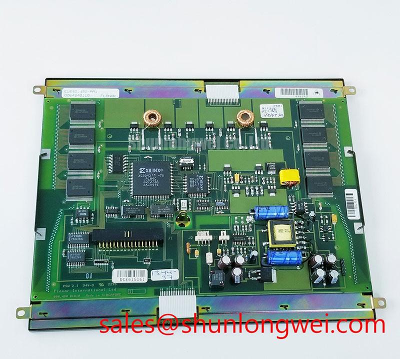
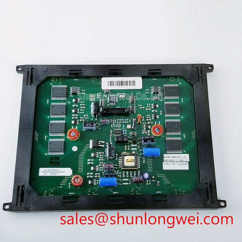
Before installation, inspect the EL640.480-AM8 module housing, display surface, connector area, and mounting points under neutral bench lighting, then compare its product marking and mechanical orientation with the original equipment documentation.
The Planar EL640.480-AM8 is an industrial electroluminescent display module. It is not a TFT LCD panel with a conventional LCD backlight. For replacement assessment, the module designation alone should not be used to assume supply rails, signal standard, pin assignment, timing, optical performance, operating temperature range, or mechanical dimensions. The system integrator should verify these requirements from the original display documentation and the equipment controller interface.
| Item | Identification |
|---|---|
| Model | EL640.480-AM8 |
| Manufacturer | Planar |
| Product Category | Industrial electroluminescent display module |
| Module Format | Electroluminescent display module |
| Specification Status | Detailed operating parameters require verification from the applicable Planar documentation |
During a cold machine start, first observe whether the EL640.480-AM8 produces a stable image, delayed transitions, uneven image motion, intermittent lines, or a normal image that changes after enclosure warm-up. These observations should be logged against the actual equipment ambient condition and power-up sequence rather than being attributed immediately to the display module.
Display response and luminance can vary with temperature, and an image that appears slow or faint during a cold start may require assessment of the display assembly, host controller timing, supply behavior, enclosure thermal path, and the original operating environment. A visual response change alone does not establish a display defect. Engineers should compare the affected system with a known stable signal path where possible and inspect whether behavior changes after controlled stabilization.
For systems using a digital display interface, design consideration requires verification of transmitter timing, data hold behavior, cable routing, grounding, and the original signaling format. A mismatch between the host controller output and the display requirement can create image instability that resembles temperature-related display degradation. The required interface standard and data mapping convention must be confirmed from original system documentation before connecting the EL640.480-AM8.
💡 Pro Tip: Keep each differential signal pair physically coupled and length matched through the cable and carrier board so pixel-clock disturbances are less likely to appear as intermittent image noise.
Inspect the display perimeter and mounting interface for evidence of enclosure stress, excessive clamp load, contamination, or cable strain. These are general integration checks rather than Planar factory limits for this model. In heavy-equipment telematics displays, vibration isolation and enclosure sealing should be evaluated at equipment level, subject to the original mechanical design.
Optical Luminance Degradation and Display-Aging Assessment
Begin any optical assessment by separating a missing image from a dim or uneven image. With the host controller confirmed active, inspect the display in a controlled low-light area and compare its visibility with the original equipment display behavior. A dim screen may involve the display module, its power supply, enable control, cable assembly, or the host power distribution.
The EL640.480-AM8 is an electroluminescent display module rather than a TFT LCD assembly with a replaceable CCFL or LED backlight. The available information does not confirm its complete drive requirements, brightness rating, dimming method, or service-life rating. These values must not be assumed from the model number. The system integrator should verify the required display supply, control inputs, connector pinout, and startup sequence from the applicable Planar documentation before considering any modification.
A CCFL-to-LED modernization is not an automatic replacement path for the EL640.480-AM8 because the module does not use a conventional LCD backlight architecture. Any change to the display or its drive electronics is a system-level engineering change that can alter optical behavior, mechanical fit, electrical loading, electromagnetic behavior, control signals, and fault detection within the original equipment. Engineers evaluating such a change should validate the display controller, illumination or display-drive method, enclosure clearances, and serviceability requirements through prototype testing.
Input supply stability also matters when a display assembly includes driver electronics. The general function of local decoupling is described in this technical reference on decoupling capacitors. Design consideration is to examine the original power distribution path, especially where cable resistance, shared loads, or machine cranking events can affect the voltage seen at the display assembly.
For a broader reference on display technology selection, inspection priorities, and industrial integration boundaries, review The Ultimate Guide to Industrial TFT LCD Technology. Although the reference focuses on TFT LCD technology, its general integration guidance can help document how the display module, controller board, enclosure, and operator viewing environment interact over extended equipment service.
Full-Screen Pattern Inspection for Display Defects and Background Uniformity
A practical receiving inspection for the EL640.480-AM8 can use controlled full-screen patterns after the host system interface has been verified. Display uniform bright, mid-level, and dark patterns appropriate to the module’s monochrome electroluminescent output, then observe for persistent bright or dark points, irregular lines, localized luminance variation, or edge shading. Record findings with the same video source and display-control state used for every sample under review.
A neutral gray or mid-level pattern can reveal nonuniform display output, while a dark pattern can help identify areas that remain visibly active. If lines or fixed image artifacts remain during different test patterns, compare the source signal, cable connection, and display behavior before isolating the fault location.
Use a flashlight at an oblique viewing angle only as a visual aid for distinguishing surface condition, image presence, and broad display-output changes. It cannot confirm an internal failure mechanism. Avoid pressing on the active area or flexing the housing during inspection because mechanical force can alter the observed image and make fault isolation less reliable.
Where the original system uses a brightness or display-drive control signal, the controller documentation should define the accepted control characteristics. Design consideration is to verify that brightness commands remain stable during normal operation and that the operator does not report visible flicker or audible noise from associated power hardware. The available EL640.480-AM8 information does not establish a specific dimming frequency or duty-cycle requirement.
For formal acceptance, use the equipment manufacturer’s approved display-defect, luminance, and viewing-condition criteria. A field inspection can identify conditions requiring further evaluation, but it should not replace the original product acceptance standard.
Aluminum Heat Spreader Sizing and Thermal Interface Placement along Narrow Display Edges
Before adding any thermal hardware around the EL640.480-AM8, inspect the existing enclosure contact surfaces, fastener locations, cable exits, airflow paths, and areas where the module may experience edge loading. A heat spreader that improves one local temperature condition can introduce mechanical stress, obstruct a connector, reduce service clearance, or alter the intended mounting plane.
Design consideration is to place thermal interface materials only where the original mechanical architecture supports controlled contact and where no display surface, cable, or connector is compressed. Material selection, thickness, contact pressure, and rail geometry must be determined through the equipment thermal design and confirmed by measurement. The available official module information does not specify a required heat spreader, interface material, mounting torque, or thermal resistance value for this model.
In equipment exposed to repeated temperature changes, assess the complete assembly rather than the display module in isolation. This includes the front bezel, rear housing, controller board, cable strain relief, power-conversion hardware, and the space available around the narrow display edges. Engineers may evaluate this module for industrial HMI or monitoring installations, including earthmoving equipment telematics consoles, subject to the original enclosure, vibration, and interface requirements.
Signal integrity should be reviewed alongside thermal placement. Conductive rails, shielding features, and mounting brackets can change the electromagnetic environment around display cables. When a differential interface is used, the host board and cable assembly should preserve the impedance and skew requirements defined by the original display and controller documentation. Verify image stability with the final enclosure closed and with adjacent equipment loads operating, rather than relying only on an open-bench test.