Content last revised on July 8, 2026
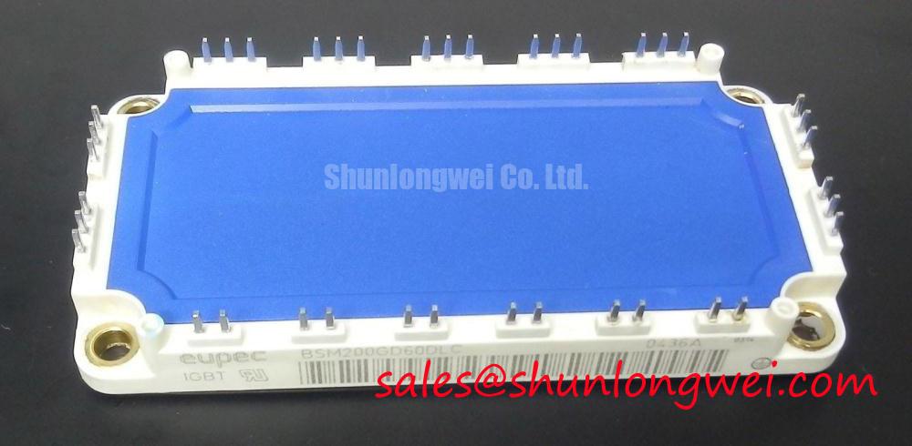
Infineon BSM200GD60DLC IGBT Module: Sixpack Topology for High-Efficiency Inverters
Are you encountering challenges with thermal management and high conduction losses in your three-phase inverter designs? This is a common bottleneck for power electronics engineers when selecting semiconductor components for industrial converters. The BSM200GD60DLC, originally developed under the Eupec brand and now supported by Infineon Technologies, is a low-loss IGBT module designed to address these concerns directly by combining high power density with optimized switching behavior. It serves as a highly efficient 600V, 200A sixpack IGBT module that minimizes conduction losses and simplifies three-phase system layouts.
What is the primary benefit of its low collector-emitter saturation voltage? Conduction losses are significantly minimized during high-current operation.
How does the integrated sixpack topology optimize system space? It integrates six IGBTs to eliminate external interconnection routing.
Frequently Asked Questions
Engineering Clarifications for System-Level Power Design
How does the low VCE(sat) of the BSM200GD60DLC affect heat dissipation?
A lower collector-emitter saturation voltage of 1.95V directly reduces conduction loss. Think of it like a narrow valve in a water pipe: a lower saturation voltage means the valve opens wider, offering minimal restriction to the current flow, keeping the system cool. This minimizes the sizing requirements for your external heatsink and enhances system-level efficiency.
What is the significance of the 8,450 A2s I2t rating for the freewheeling diode?
This rating indicates the diode's capacity to absorb surge energy during transient overcurrent events, such as motor start-up or sudden load changes, preventing thermal runaway and safeguarding the system against catastrophic failure under high stress.
Can this module be directly integrated with high-frequency PWM controllers?
Yes, the module is optimized for fast switching with a typical turn-off delay time of 253 ns (at 25°C) and can operate efficiently within typical industrial switching frequency bands. Designers must ensure that the gate driver provides appropriate dead-time settings to prevent shoot-through.
How does the thermal resistance of 0.18 K/W impact heatsink design?
A junction-to-case thermal resistance (Rth(j-c)) of 0.18 K/W acts as a fast heat highway, allowing efficient heat removal from the IGBT chip. Engineers can use this parameter for thermal sizing calculations to ensure the junction temperature stays below 125°C under continuous load.
Key Parameter Overview
Decoding the Specs for Enhanced Thermal Reliability
| Parameter | Symbol | Value | Engineering Value & Description |
|---|---|---|---|
| Collector-Emitter Voltage | VCES | 600V | Maximum blocking voltage, suitable for 3-phase line rectifiers. |
| Nominal Collector Current | IC | 200A | Continuous current handling capacity at case temperature of 45°C. |
| Peak Collector Current | ICRM | 400A | Repetitive peak current allowed for 1 ms pulse width. |
| Saturation Voltage | VCE(sat) | 1.95V (typ) | Saturation voltage at 200A, determining conduction losses. |
| Total Power Dissipation | Ptot | 700W | Maximum power dissipation per switch at 25°C. |
| Isolation Test Voltage | VISOL | 2.5 kV | RMS isolation voltage for safety barrier compliance. |
| Thermal Resistance | Rth(j-c) | 0.18 K/W | Transistor junction-to-case thermal resistance. |
Download the BSM200GD60DLC datasheet for detailed specifications and performance curves.
Technical & Design Deep Dive
Mitigating Switching Losses and Conduction Efficiency
To optimize inverter efficiency, engineers must carefully manage both switching and conduction losses. The BSM200GD60DLC employs a fast-switching trench-field-stop style IGBT technology designed to control the tail current during turn-off phases. With a turn-on energy loss of 4.6 mJ (Eon) and turn-off energy loss of 6.3 mJ (Eoff) per pulse at 125°C, this module maintains excellent thermal margins even under continuous high-frequency modulation. In high-power designs, minimizing stray inductance is critical to preventing voltage spikes. This module features a low internal stray inductance (LσCE) of 28 nH, which minimizes the need for bulky snubber circuits. Understanding how electrical parameters vary across temperatures is crucial when decoding IGBT datasheets.
To visualize this, think of the thermal resistance of 0.18 K/W as a high-speed thermal highway. Just as adding lanes to a highway accelerates traffic flow, a lower thermal resistance ensures that the heat generated inside the silicon junction is quickly routed away to the heatsink. This prevents localized hot spots that could compromise the module’s Safe Operating Area (see more on Safe Operating Area). System protection schemes are critical to avoid common failure modes, which are discussed in detail in our guide on IGBT failure analysis. For a broader context on modular layouts, see our in-depth analysis of IGBT modules.
Application Scenarios & Value
Achieving System-Level Benefits in Industrial Motor Drives
For 380V industrial systems requiring high current handling and minimal switching losses, the 600V BSM200GD60DLC module offers a highly optimized sixpack solution. In variable frequency drives (VFDs) and servo drives, the module handles transient overloads during motor startup, where collector currents can surge up to 400A. The sixpack configuration integrates all three phases of the inverter bridge in a single housing, streamlining mechanical design and reducing the loop area of high-current paths. This directly minimizes electromagnetic interference (EMI) and simplifies compliance with EMC standards.
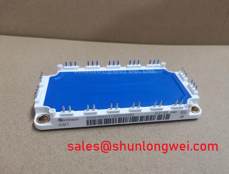
In online uninterruptible power supplies (UPS) and renewable energy systems, the low saturation voltage minimizes power losses during the main conduction cycle, resulting in reduced cooling requirements and higher overall system reliability. When designing power systems of different scales, engineers can evaluate options across the product family. For smaller load configurations, the related BSM100GD60DLC offers a 100A rating in a similar topology. Conversely, for systems requiring higher voltage blocking capabilities, the BSM150GT120DN2 provides a 1200V rating, while the BSM300GA120DN2 supports up to 300A for higher-power configurations.
Selecting the right power semiconductor is a strategic decision that affects not only system-level efficiency but also the overall thermal architecture and long-term operating costs. By analyzing the switching losses, transient response, and mechanical footprint of the BSM200GD60DLC, engineering teams can design robust motor control solutions that meet today's stringent industrial energy mandates.