Content last revised on October 1, 2026
SKM450GB12T4D1 Gate Tuning: Investigating dv/dt Cross-Conduction
| Model | SKM450GB12T4D1 |
|---|---|
| Manufacturer | Semikron |
| Product category and housing | IGBT module, Semitrans |
| Rated voltage | 1200 V (Official Specification) |
| Rated current | 450 A (Official Specification) |
Capture the off-state gate-to-emitter waveform while the opposite switch commutates, then compare any voltage excursion with the driver’s actual turn-off level. A gate pulse that follows a fast switching edge may point to Miller coupling, common-emitter impedance, driver behavior, or measurement pickup; the waveform alone does not establish shoot-through. Repeat the capture with a short, appropriately rated probe connection and compare it with a known-good operating phase.
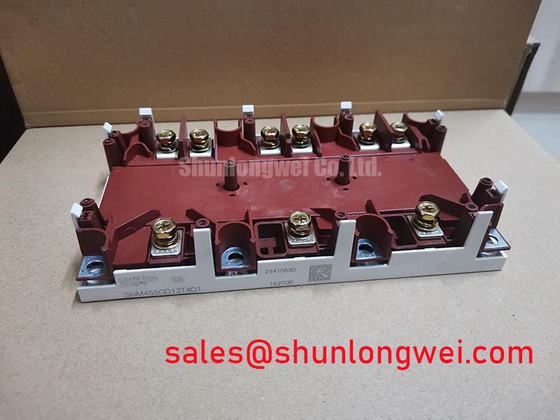
The SKM450GB12T4D1 is a Semikron 1200 V, 450 A IGBT module in a Semitrans housing (Official Specifications). Those ratings identify the module for an initial electrical and mechanical comparison. They do not specify a gate-bias setting, switching speed, or permissible stray inductance for the assembled converter. During repair, compare the installed driver schematic and switching waveforms before changing gate components.
For high dv/dt operation, an active Miller clamp is a Design Consideration where the driver supports one: its low-impedance path can help hold the gate off as collector voltage changes. Negative off-state bias is another system-level option, but its value must come from driver capability, module documentation, and switching tests rather than a preset attached to this part number. The discussion of Evolution of Negative Off-Bias Gate Drive Circuits provides background for evaluating that trade-off. Confirm that the chosen turn-off scheme remains effective through driver supply transients and fault recovery.
Trace the gate return against the power-current path on the actual assembly. Where a separate auxiliary emitter connection is documented, route the driver return to that connection rather than assuming a main power terminal provides an equivalent sensing reference. Keep the gate loop compact to limit parasitic inductance and inspect turn-on and turn-off ringing at the module terminals. Any change to gate resistance or damping should be verified against switching loss, voltage overshoot, and driver temperature in the finished equipment. Semikron-Danfoss’s SEMITRANS product information provides housing-family context; the installed module’s connection drawing governs terminal identification.
SKM450GB12T4D1 Driver Isolation and High-Side Supply Checks
Probe the driver supply and gate signal during the switching event that produces the fault, looking for a supply dip, an unintended pulse, or a delayed turn-off. Compare the driver input with its output: a pulse present only after the isolation stage directs attention to the driver, its supply, or common-mode disturbance, while a pulse already present at the input calls for inspection further upstream. Use measurement equipment and probe arrangements suitable for the converter’s voltage environment.
An optocoupler and a digital isolator using a coreless-transformer architecture are driver design choices, not properties established by the SKM450GB12T4D1 ratings. Isolation-barrier performance and common-mode transient immunity belong to the selected driver and its complete implementation. As a Design Consideration, compare the driver manufacturer’s isolation and transient specifications with the converter’s measured conditions, then check for false output transitions during switching. Neither the module’s 1200 V rating nor its Semitrans housing establishes a driver isolation rating or an equipment safety approval.
If the installed high-side driver uses a bootstrap supply, inspect its capacitor voltage across the longest operating interval without refresh. Capacitor selection must account for gate charge, driver quiescent consumption, leakage, switching frequency, and the allowable supply-voltage swing. Check that the charging path can restore the supply under the converter’s operating pattern and examine bootstrap-diode recovery during fast transitions. These are Engineering Recommendations for evaluating the driver circuit, not factory capacitor values for this module.
Separate a supply-integrity problem from a module fault before removing hardware. Compare high-side and low-side gate amplitudes under the same test conditions, inspect connector seating and return-path continuity, and look for noise coincident with the fault indication. If desaturation protection operates, capture the gate command, collector-to-emitter voltage, and driver fault output together. The driver’s blanking interval, fault response, and soft turn-off behavior must be checked against its own design and the module’s applicable short-circuit operating limits; the supplied voltage and current ratings do not define those limits.
SKM450GB12T4D1 Thermal Stress in Bidirectional Power Conversion
Trend heat-sink temperature and module current through charging and discharging transitions, then compare recurring temperature rises with the converter’s load history. In a utility-scale centralized battery energy storage PCS, this is a useful compatibility and maintenance assessment, not an assertion that the module was designed specifically for that equipment. The current direction and conduction path can change with operating mode, so inspect the actual circuit schematic before attributing a temperature change to one switch position.
The 450 A rated current (Official Specification) is a starting point for part identification, not a continuous-current allowance at every heat-sink temperature or switching frequency. Junction temperature depends on conduction loss, switching loss, cooling conditions, and the assembled thermal path. During an equipment evaluation, compare measured case or heat-sink temperatures and operating waveforms with the limits and test conditions in the applicable Semikron documentation. The Semikron-Danfoss power modules catalog is a useful route to manufacturer product documentation.
Inspect the heat sink for blocked airflow and uneven contact marks when a phase runs hotter than its peers. Check the condition and coverage of the thermal interface material when the module is removed; apply and fasten it according to the applicable assembly instructions rather than assigning a generic paste thickness or bolt torque to this housing. Recheck terminal connections with the equipment isolated, using the specified fastening procedure for the installed hardware. A thermal pattern that persists after cooling-path maintenance warrants waveform and current-balance checks, not an immediate assumption of internal module damage.
Maintenance Note: Isolate the converter before checking terminal tightness, and trend contact temperature and cooling airflow after reassembly.
For cyclic loading, record temperature trends across comparable operating periods and investigate changes in the trend alongside fan condition, filters, heat-sink cleanliness, and thermal-interface condition. A shorter or longer service interval cannot be inferred from the 1200 V and 450 A ratings alone. Let measured operating conditions and the equipment maintenance plan determine inspection frequency.
SKM450GB12T4D1 Busbar Geometry and Current-Sharing Faults
Compare switching waveforms and current measurements across parallel paths before adjusting a gate resistor or replacing a module. A difference may reflect unequal busbar inductance, gate-loop routing, connection resistance, or measurement placement. Inspect the positive and negative DC-link paths for comparable geometry, then check each module’s gate drive at its own referenced terminals during the same switching event.
Symmetrical busbar routing is a Design Consideration for limiting unequal transient voltage and current distribution. Keep the outgoing and return current paths closely coupled where the equipment layout permits, while maintaining clearances required by the complete system design. During turn-off, compare the measured collector-to-emitter peak with the DC-link voltage and the module’s 1200 V rated voltage (Official Specification). The system engineer must determine an acceptable operating margin from the converter’s transients and the applicable module limits.
Static and dynamic current sharing require different checks. Collector-to-emitter saturation behavior can influence steady-state sharing, but no temperature-coefficient value or sharing guarantee is established by the supplied specifications. Compare conduction voltage under controlled, comparable current and temperature conditions if that behavior is relevant to the installed circuit. For dynamic balance, inspect gate-command timing, gate-return routing, and the switching waveforms of each path. Matching a busbar without checking the drive paths can leave the original imbalance unresolved.
When assessing another Semikron part, use its own ratings, terminal drawing, housing dimensions, and thermal requirements rather than treating a shared brand as proof of interchangeability. The SKM100GB176D can serve as a separate comparison reference, but it is not established here as a direct replacement for SKM450GB12T4D1. Close the fault investigation with measurements from the repaired assembly: gate waveforms, DC-link transients, path currents, and temperatures under the operating modes that originally produced the alarm.