Content last revised on October 7, 2026
Regenerative DC-Bus Voltage Surge Dissipation during Rapid Machine Deceleration
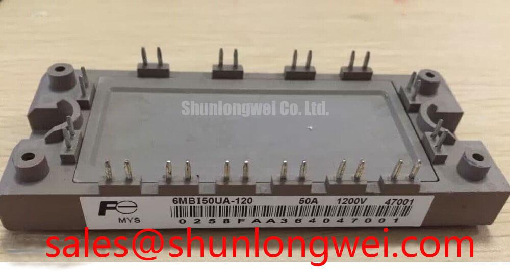
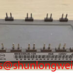
With the inverter welder or induction-heating supply isolated and its DC link verified discharged, compare the installed module’s terminal markings with the equipment schematic before measuring any cold-state junctions. The 6MBI50UA-120 is listed as a Fuji Electric IGBT Module with a rated current of 50.0 A (Official Specifications supplied for this listing). The listed package is Module (Official Specification). Verify the voltage rating against the manufacturer’s data and original equipment documentation before installation; do not infer it solely from the model designation or the listing.
Begin with the equipment topology, not a braking-resistor estimate. An industrial inverter welder or medium-frequency induction-heating supply can contain a DC link, switching bridge and protective circuits, but that does not establish that its bus operates regeneratively. Trace the schematic to determine whether the machine returns energy to the DC link during a specified operating transition and whether a braking switch and ballast resistor are actually present. The 6MBI50UA-120 should be assessed against its documented position in that circuit rather than assigned a braking role from its IGBT-module category.
Where the system does use a braking path, a rising bus-voltage trace is more informative than a damaged switch alone. Record the bus voltage during the relevant transition, check when the controller commands the braking switch, and compare the measured peak with the equipment’s specified limits. Inspect the resistor circuit for an open connection, altered resistance or interrupted thermal protection. Resistor pulse capacity, switch loading and permissible bus voltage are system-level decisions; the module’s verified voltage rating is not a complete braking-circuit design limit.
For incoming bench checks, use the terminal diagram applicable to the exact installed assembly. A multimeter diode test can help compare accessible antiparallel-diode paths across similar modules, provided probe polarity and meter behavior are recorded. It cannot establish blocking-voltage capability or prove that an IGBT will switch correctly under load. Compare readings with the equipment documentation or a known-good assembly rather than treating one cold-state voltage drop as a universal pass threshold.
Planar Symmetrical Busbar Geometry and Switching Overshoot
Inspect the physical path between the DC-link capacitors, module power terminals and any snubber before judging the replacement. A long or uneven commutation loop can add switching overshoot even when the steady bus voltage appears acceptable. As a Design Consideration, keep outgoing and return current paths closely coupled where the equipment layout permits, and assess the assembled path with switching measurements. A particular stray-inductance target cannot be assigned to this module without a verified system design and test conditions.
During a controlled switching test, the observed collector-emitter peak reflects both DC-link voltage and the voltage developed across loop inductance as current changes. That relationship explains why a busbar or snubber change must be evaluated at the switch terminals, not inferred from the capacitor-bank reading. Check the probe arrangement as well: a long measurement ground lead can make a transient look different from the voltage actually present at the device. The system designer should select snubber components from measured waveforms, capacitor ratings and the applicable circuit documentation.
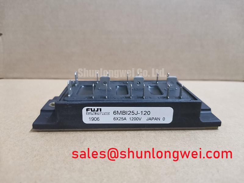
Line-frequency ripple, phase-angle control and RC suppression belong to different parts of a power system. If the equipment includes controlled rectification, inspect its firing behavior and DC-link ripple separately from high-frequency switching spikes. An RC network may affect a measured transient, but its presence does not confirm that the bridge is adequately protected. For related module comparison, 6MBI50J-120 is a reference point for checking documented ratings, terminal layout and mechanical fit; a similar model name does not establish interchangeability.
Static and Dynamic Current Distribution across Paralleled IGBT Switches
If the equipment parallels switch positions, first establish which devices actually share current. Follow the busbar connections and gate-drive schematic, then inspect each branch for unequal contact condition, conductor geometry or gate wiring. The supplied specifications identify the 6MBI50UA-120 as a 50.0 A module (Official Specification supplied for this listing); they do not specify its current-sharing behavior in a parallel assembly.
A positive temperature coefficient of on-state voltage is sometimes used in discussions of static IGBT current sharing, but its usefulness depends on the device’s characterized operating region and thermal conditions. Do not assume that it will correct an asymmetric installation. Dynamic sharing also depends on gate-drive timing and power-loop impedance. Compare branch-current waveforms under controlled conditions if the equipment provides safe measurement access, and investigate differences before changing drive components. The applicable Fuji Electric device data and the system design should determine acceptable limits.
Before powered testing, document cold-state gate-to-emitter resistance and accessible diode-test paths with consistent meter polarity. An unexpected difference calls for checking connected drive circuitry and the relevant terminal identification; an in-circuit reading is not necessarily a module-only reading. A gate-threshold measurement requires a defined test circuit and current criterion, so a casual multimeter reading should not be reported as an official threshold value. For a broader testing framework, the Field Engineer’s Handbook provides context for recording measurements and separating observations from failure conclusions.
Differential Gate-Emitter Loop Routing to Suppress Ground-Bounce Noise
Trace each gate-drive output and its emitter return as a pair. Where an assembly provides an auxiliary emitter terminal, verify its identity from the exact terminal drawing before using it as a driver return; an auxiliary connection must not be assumed from the package name. As a Design Consideration, routing the drive return separately from the main load-current path can reduce the influence of common-path voltage on the applied gate-emitter signal. The final routing and protective settings remain system-specific.
On the bench, compare commanded drive transitions with gate-emitter voltage measured at the relevant terminals during a controlled test. If unwanted movement appears during another switch’s transition, examine probe placement, return routing, connector condition and gate-loop symmetry before attributing it to the module. Gate-drive guidance in the Fuji Electric V-Series IGBT Application Manual is useful for understanding general switching and layout mechanisms; its examples should not be treated as verified device-specific limits for 6MBI50UA-120.
💡 Bench Tip: Keep the gate protected from incidental contact during cold-state checks, and record probe polarity before comparing diode-mode readings. If the equipment schematic places another module in the same power subsystem, 6MBI300U-120 can be reviewed as a separate topology reference. Verify each device’s documented electrical role and connections independently before restoring power.