Content last revised on June 25, 2026
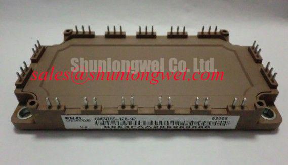
Fuji Electric 6MBI75S-120-01 1200V 75A Inverter IGBT Module
The 6MBI75S-120-01 is a high-performance six-pack IGBT module designed for industrial power conversion applications that demand high thermal efficiency and switching precision. By integrating six IGBTs into a single compact package, this module simplifies 3-phase inverter design while maintaining the ruggedness required for harsh industrial environments.
For industrial motor drives requiring high thermal reliability in a 6-pack configuration, the 6MBI75S-120-01 provides an excellent power-to-footprint ratio. This module effectively bridges the gap between discrete components and high-power press-pack modules, offering 1200V of collector-emitter voltage and 75A of continuous collector current. It addresses the engineering challenge of managing switching losses at high frequencies through its optimized carrier distribution, which significantly reduces the energy dissipated during transition states. Key benefits include enhanced system longevity due to reduced thermal stress and a simplified mechanical layout for easier assembly. By utilizing its soft-recovery free-wheeling diode (FWD), engineers can effectively suppress electromagnetic interference (EMI) without the need for bulky external filtering components.
Key Parameter Overview
Decoding the Specifications for Enhanced Thermal Reliability
The technical specifications of the 6MBI75S-120-01 reflect its design intent for high-voltage, medium-current switching. Understanding these grouped parameters is essential for calculating system-level efficiency and selecting appropriate gate drivers.
| Category | Parameter | Value |
| Maximum Ratings | Collector-Emitter Voltage (Vces) | 1200V |
| Continuous Collector Current (Ic) | 75A | |
| Total Power Dissipation (Pc) | 600W | |
| Electrical Characteristics | Saturation Voltage (Vce sat) | 2.30V (Typical) |
| Gate-Emitter Threshold (Vge th) | 6.0V (Typical) | |
| Switching Dynamics | Turn-on Time (ton) | 0.35µs |
| Turn-off Time (toff) | 0.45µs | |
| Isolation | Isolation Voltage (Viso) | 2500V AC (1 min) |
Download the 6MBI75S-120-01 datasheet for detailed specifications and performance curves.
A useful way to conceptualize the Saturation Voltage (Vce sat) is to view it as a high-flow plumbing valve. A lower Vce(sat), like the 2.3V offered here, represents less "friction" or pressure drop as the current flows through the device, which directly translates to less heat generated during the conduction phase.
Application Scenarios & Value
Achieving System-Level Benefits in High-Frequency Power Conversion
The 6MBI75S-120-01 is a cornerstone component in Variable Frequency Drives (VFD) and Uninterruptible Power Supplies (UPS). In a typical 400V industrial motor drive scenario, engineers often face the challenge of excessive heat buildup within sealed enclosures. The 6MBI75S-120-01 solves this by optimizing the balance between conduction and Switching Loss, allowing for a smaller heatsink volume. This is particularly critical in space-constrained cabinets where airflow is limited.
In the context of renewable energy, this module serves effectively in the PFC stage of solar inverters. Its ability to handle 75A continuously ensures stability during peak generation hours. Furthermore, for systems requiring a dual-module configuration rather than a 6-pack, the 2MBI75S-120 offers a similar current rating in a different topology to better suit modular inverter designs. Integrating this module into a design following high-efficiency power system standards ensures compliance with modern energy regulations like IEC 61800-3 for drive systems.
Technical & Design Deep Dive
Analyzing the Module Architecture for Long-Term Performance
The internal architecture of the Fuji Electric S-series modules focuses on reducing stray inductance. In high-speed switching, stray inductance causes voltage spikes ($V = L cdot di/dt$) that can exceed the 1200V rating and lead to catastrophic failure. The 6MBI75S-120-01 utilizes a low-inductance internal bus bar structure to mitigate this risk, providing a safer margin during high-current turn-off events. This is a critical factor when designing for Electric Vehicle (EV) chargers or high-power induction heating systems.
The thermal management of the module is supported by a copper baseplate and a highly reliable DBC (Direct Bonded Copper) substrate. This structure ensures that the Thermal Resistance from the junction to the case is minimized. To visualize the Isolation Voltage of 2500V AC, consider it a high-voltage safety barrier. Much like a reinforced concrete levee protects a city from a surging river, this ceramic isolation layer prevents the high-power collector current from reaching the sensitive low-voltage control circuitry, even during severe electrical transients.
Frequently Asked Questions
What is the maximum short-circuit withstand time for this module?
The 6MBI75S-120-01 is rated for a short-circuit withstand time of 10µs at a collector-emitter voltage of 800V. This provides a sufficient window for modern gate drive protection circuits to detect an overcurrent event and safely shut down the module before thermal destruction occurs.
How does the Vce(sat) of 2.3V impact the cooling requirements of my system?
The 2.3V Saturation Voltage directly determines the conduction loss. At a full 75A load, the device dissipates roughly 172.5W of heat per IGBT during the ON state. This relatively low value allows for higher power density, but engineers must still ensure that the thermal interface material (TIM) and heatsink can maintain the junction temperature below the 150°C limit. For a broader overview of these trade-offs, see our field engineer's handbook on reliability.
Can this module be driven with a simple 0V/15V gate signal?
While a 0V turn-off signal is possible, it is highly recommended to use a negative gate voltage (e.g., -5V or -10V) for the turn-off state. This prevents accidental turn-on caused by Miller capacitance ($Cgc$) spikes during the high $dv/dt$ switching of adjacent phases in the 6-pack configuration, a common phenomenon in industrial Inverter bridges.
From an engineering perspective, the 6MBI75S-120-01 represents a mature, stable technology choice for power stages where reliability is the primary metric. When implementing this module, focus on minimizing the gate loop area and selecting a gate resistor ($Rg$) that balances switching speed with voltage overshoot. Proper decoupling with high-frequency snubber capacitors directly across the P and N terminals is mandatory to realize the full performance potential of this Fuji Electric module.