Content last revised on October 17, 2026
6MBI75U4B-120 Incoming Inspection and Electrical Specifications
- Isolate the DC supply, verify discharge, and match the 6MBI75U4B-120 terminal markings to the equipment schematic before connecting test leads.
- Record cold diode-mode readings across corresponding power paths with consistent probe polarity, temperature, and gate conditions.
- Inspect the module mounting surface, heatsink contact area, terminal hardware, and existing thermal interface imprint before reassembly.
- Separate power-terminal checks from insulation testing, using the specified test connections and manufacturer-approved insulation procedure.
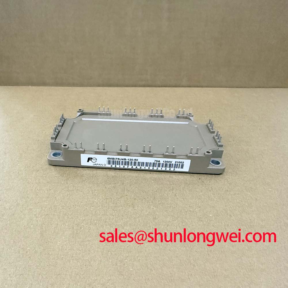
The Fuji Electric 6MBI75U4B-120 is an IGBT module rated at 1200 V and 75 A, with the continuous current rating specified at a case temperature of 80°C. Incoming inspection should establish terminal identity and repeatable static measurements before the module enters a powered test fixture. A handheld meter can reveal differences between comparable paths, but its low-current readings do not reproduce the rated-current characteristics below.
Official Specification: The electrical values in this table must be read with the manufacturer's complete test conditions. Mechanical dimensions, terminal assignments, mounting torque, insulation test voltage, and additional electrical and switching-test conditions require the applicable manufacturer datasheet.
| Parameter | Symbol | Condition | Value |
|---|---|---|---|
| Collector-emitter voltage | VCES | Junction temperature 25°C | 1200 V |
| Continuous collector current | IC | Case temperature 80°C | 75 A |
| Collector-emitter saturation voltage | VCE(sat) | Collector current 75 A; junction temperature 125°C; gate voltage as specified in the datasheet | 1.80 V typical; 2.20 V maximum |
| Freewheeling diode forward voltage | VF | Forward current 75 A; junction temperature 125°C | 1.80 V typical; 2.20 V maximum |
| Turn-on switching energy | Eon | Collector current 75 A; DC supply 600 V; additional test conditions apply | 10.0 mJ |
| Turn-off switching energy | Eoff | Collector current 75 A; DC supply 600 V; additional test conditions apply | 11.5 mJ |
| Junction-to-case thermal resistance | Rth(j-c) | Per IGBT | 0.24 K/W |
| Short-circuit withstand time | tsc | DC supply below 800 V; gate-emitter voltage 15 V; complete datasheet test conditions apply | At least 10 µs |
💡 Bench Tip: Use ESD-controlled handling and discharge the gate through the approved fixture before comparing cold readings with a known-good module under identical test conditions.
Preventing Spurious Faults: Heatsink Surface Flatness and Thermal Grease Guidelines for 6MBI75U4B-120
Inspect the heatsink contact area for raised burrs, embedded debris, residual interface material, and distortion before evaluating a temperature-related trip. As a Design Consideration, uneven contact can increase the temperature difference between the module case and cooling surface. A normal heatsink sensor reading therefore does not establish that every area beneath the module has an effective thermal path.
Assess the module baseplate profile against the mounting specification, distinguishing permitted curvature from damage. Do not flatten the baseplate by force or remove material to obtain an apparently perfect contact print. Clean the mating surfaces with a compatible process, then inspect them under suitable lighting. Retain photographs of the original interface imprint when investigating repeated thermal alarms; uneven transfer can help identify an assembly issue without proving that the semiconductor itself has failed.
As an Engineering Recommendation, apply thermal interface material through a controlled process that produces continuous coverage without excessive accumulation. Final thickness depends on the specified material, surface condition, mounting geometry, and compression during assembly. A generic grease thickness should not become an acceptance limit for this module. Check the resulting coverage using the approved assembly method rather than estimating it from the amount squeezed around the edges.
Tighten mounting fasteners progressively in a diagonal sequence with a calibrated tool, using the applicable module and equipment torque requirements. Support the assembly so that busbars and cables do not pull the terminals into position while the baseplate is being secured. Maintain the equipment's required electrical clearances around mounting hardware, exposed conductors, and adjacent structures. Terminal loading and heatsink contact deserve separate inspection because correcting one does not establish the condition of the other.
The 0.24 K/W per-IGBT junction-to-case thermal resistance is an Official Specification for that thermal path. It does not include the interface layer or heatsink. For changing loads, steady thermal resistance alone cannot describe peak junction temperature; an Engineering Recommendation is to evaluate the loss waveform with the applicable transient thermal impedance data. Case-temperature measurements can support this assessment when sensor placement and thermal lag are considered.
After reassembly, compare temperature trends at repeatable operating points while recording coolant or ambient conditions and load. A changed temperature pattern may support further inspection of mounting contact, cooling performance, or current sharing. Preserve those conditions in the service record so that the next measurement remains comparable.
Field Diagnostics & Commissioning: Four-Quadrant Power Flow in Converters Using 6MBI75U4B-120
Trace the DC terminals, phase connections, and gate-emitter pairs against the circuit diagram before interpreting current direction. As a Design Consideration, diode-mode measurements should follow the documented internal circuit, with external parallel paths isolated where necessary. Record both probe orientations and compare equivalent branches. Unexpected readings can involve connected circuitry, residual gate charge, contact resistance, or a damaged device, so investigate the measurement path before assigning a cause.
The specified diode forward voltage of 1.80 V typical and 2.20 V maximum applies at 75 A and 125°C junction temperature. A handheld meter operates under different conditions and should not be judged against those values. Similarly, a cold continuity check does not measure the specified collector-emitter saturation voltage. Rated-current verification requires a suitable fixture with controlled current, temperature, pulse conditions, and measurement connections.
For compatibility assessment, engineers may evaluate this module in commercial string inverter or micro-grid energy storage equipment when the original power-stage topology, cooling arrangement, gate drive, and mechanical interfaces match the installation requirements. Four-quadrant operation concerns the assembled converter and its controls. Battery charging and discharging paths must be traced through the actual converter stages; the module designation alone does not establish a direct battery interface or bidirectional system capability.
As an Engineering Recommendation, inspect the complete commutation loop when investigating switching overshoot. Keep outgoing and return power paths closely coupled where the assembly permits, and assess snubber connections as part of that loop. Placement should reduce the inductance seen by transient current while preserving required electrical clearances. The acceptable arrangement is determined by measured switching behavior, bus voltage, and the equipment's component limits.
During controlled commissioning, correlate current direction with gate commands and collector-emitter waveforms. Probe connections should have suitable voltage ratings and adequate common-mode performance. Compare transitions during both power-flow directions because the conducting semiconductor path and diode recovery conditions can change. Capture case temperature alongside the electrical measurements when assessing repeated load changes.
The Official Specification gives switching energies of 10.0 mJ turn-on and 11.5 mJ turn-off at 75 A and 600 V, subject to the complete datasheet test conditions. These are energy values, not continuous power ratings. As a Design Consideration, operating losses depend on switching frequency, current waveform, temperature, and drive conditions. The explanation of RMS current helps assess resistive losses in conductors, while IGBT conduction assessment requires the device voltage-current characteristics.
When comparing the 6MBI75U4B-120 product configuration with the 2MBI300VW-120D-51, compare circuit arrangement, terminal positions, switching characteristics, cooling requirements, and mounting dimensions before considering interchangeability. Where a separate converter or active rectification stage includes a device such as the 2MBI200S-120-52, its role must follow that stage's schematic and control requirements. Neither comparison establishes a direct replacement or a required companion device.
6MBI75U4B-120 Operational Boundaries: Evaluating Fault-Clearing Dynamics and Type-I/II Desaturation Protection
Measure the complete protection response from fault onset through detection, driver action, and current extinction. The short-circuit withstand specification of at least 10 µs applies under the manufacturer's complete test conditions, including DC supply below 800 V and gate-emitter voltage 15 V. It must not be treated as a universal timer setting or evidence that every fault waveform is acceptable for that duration.
As a Design Consideration, a Type-I short circuit begins when an IGBT turns on into an existing fault, while a Type-II event develops after conduction has begun. Detection behavior can differ because the initial collector voltage, current trajectory, and gate state differ. Evaluate the relevant fault cases using the manufacturer's short-circuit operating limits and the equipment's approved test procedure.
Desaturation protection must distinguish the normal turn-on transition from a fault without consuming excessive protection time. Review blanking behavior, sensing connections, propagation delays, and the driver's response to a fault input. An Engineering Recommendation is to assess these together with the actual gate waveform; a controller timestamp alone does not show when the semiconductor current has stopped.
Controlled or staged turn-off can reduce the current fall rate and associated inductive overshoot, but the discharge profile must be established for the driver, module, and power loop. Inspect collector-emitter voltage and gate-emitter voltage during the event. The Precision Gate Drive Design reference provides supporting context for reviewing gate-loop layout and protection behavior.
Verify dead time at the device gate terminals under the relevant operating conditions. As a Design Consideration, driver propagation differences, switching transitions, and parasitic coupling affect overlap risk. IGBT gate control concerns gate charge and gate-emitter voltage.
For insulation checks, use the prescribed terminal grouping, test voltage, duration, and acceptance criterion, with sensitive external circuits disconnected as required by the procedure. Semiconductor blocking voltage and insulation withstand assess different paths. Record the tested connections and environmental conditions, then resolve any abnormal result through inspection and repeat testing under the approved procedure before reconnecting the gate driver.