


Content last revised on September 30, 2026
Benchtop Waveform Tuning: Thermal Feedback and Gate Balance on 7MBP150KB060
With the drive isolated and its DC link discharged, measure cold-state resistance between accessible power terminals and compare each path with the equipment schematic and a known-good assembly. Record the meter polarity and readings rather than treating one resistance value as a pass criterion. An unexpectedly low reading can involve a connected snubber, rectifier or other circuit path; disconnect the module only where the service procedure permits a separate measurement.
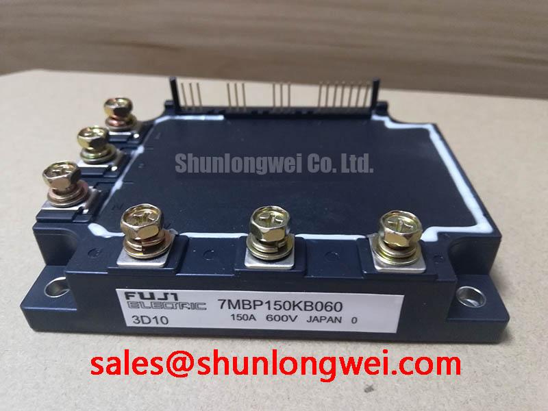
The 7MBP150KB060 carries an Official Specification of 600 V rated voltage and 150 A rated current. Those figures establish identification and rating boundaries, not an allowable DC-link setting or continuous current for every heatsink. For a heavy-duty variable frequency AC motor drive under evaluation, match the installed part number, terminal arrangement, mounting footprint and control connections to the original assembly before interpreting a waveform. A meter check can expose an obvious short; it cannot establish switching health under load.
On a powered test bench, capture the gate-command signal alongside the relevant collector-to-emitter waveform at a controlled operating point. Compare turn-on and turn-off behavior across equivalent switching paths. A changed plateau, delayed transition or irregular ringing is a reason to inspect the driver supply, gate return path and local connections together, not to assign the fault to the module from one trace. Observe the measurement instrument’s voltage and isolation limits when probing a live power stage.
Design Consideration: Where an equipment topology shares current between parallel switching paths, similar gate-loop geometry helps reduce dynamic imbalance. Static sharing also depends on each device’s temperature-dependent conduction behavior; a specific positive temperature coefficient for this module should not be assumed without the applicable characteristic curves. Route and test the installed gate circuits as the equipment design requires, then compare current and temperature under representative load.
Fuji Electric’s PIM product information provides context for the module family. It does not replace the exact unit’s terminal drawing when tracing a drive fault. Keep that distinction clear during a rapid repair: a matching rating on a label is useful, but a mismatched control or power connection can invalidate an otherwise convincing bench comparison.
7MBP150KB060 Thermal-Electrical Optimization: Commutation Loop Inductance
Probe the turn-off voltage at the power stage while monitoring DC-link voltage at the same operating point; the difference reveals switching overshoot that a static bus reading misses. Repeat the capture at representative load conditions and check whether the peak remains within the 600 V rated boundary. Probe placement matters: a long measurement ground path can add apparent ringing, so verify the trace with an appropriate high-voltage measurement setup before changing hardware.
Design Consideration: Parasitic inductance in the commutation path raises the voltage seen during a rapid current change. Keep the outgoing and return current paths close where the equipment layout allows, and inspect bolted bus connections for looseness or damage. If the assembly uses a laminated or planar busbar, compare its installed geometry with the original arrangement. The acceptable loop inductance is a system result, determined by switching tests against the actual DC-link voltage and device rating, not by a universal layout target.
A snubber can affect the measured peak and ringing, but its component values cannot be selected from the module’s voltage and current ratings alone. Check fitted capacitors and connections against the equipment schematic, measure the waveform after any repair, and let the system design determine whether a change is warranted. Fuji Electric’s V-Series IGBT Application Manual is a useful source for general switching and installation principles; its examples should not be treated as unverified 7MBP150KB060 settings.
Switching losses and cooling demand must be assessed together. At the equipment’s intended switching frequency, examine heatsink temperature trends, fan operation and airflow obstruction while recording load current. If temperature rises after a frequency or control change, compare switching waveforms as well as the cooling path. The 150 A Official Specification does not establish a permissible current at every ambient temperature or switching frequency.
Trace the surrounding power circuit before ordering a related module. In equipment where a separate switching stage is documented, 2MBI150NC-060-10 is a distinct module to evaluate against that stage’s schematic, rather than an assumed internal element of the 7MBP150KB060. Confirm each part’s electrical role and connections at the equipment level.
Field Diagnostics and Commissioning: Transient Heating in 7MBP150KB060 Circuits
Log current, case or heatsink temperature, and the timing of the trip during a repeatable load change. A module that remains stable at light load but trips during a pulse calls for checks of cooling contact, current sensing and protection timing before any single cause is assigned. Inspect fault history alongside the captured waveforms; a thermal event and a switching overvoltage can appear close together in a drive log.
Transient junction heating cannot be calculated reliably from the 150 A rating alone. It requires a verified transient thermal impedance curve, the relevant loss data and the pulse profile. Design Consideration: If those data are available for the exact device, the system engineer can estimate pulsed junction temperature and check the result against the applicable limits. Without them, use measured operating trends to narrow the fault, rather than presenting a modeled temperature as a factory rating.
Check the driver supply and switching commands when a fault occurs under acceleration or reversal. In a bridge circuit, overlapping commands can create a hazardous current path; compare actual gate waveforms with the controller’s intended dead-time behavior. If the equipment uses bootstrap supplies, inspect their charge path and recovery behavior during its switching pattern. Do not infer a bootstrap circuit, negative gate bias or a separate emitter-sense terminal from the 7MBP150KB060 model name. Follow the installed schematic and terminal drawing before testing those features.
Where desaturation detection and soft turn-off are implemented in the surrounding driver, capture the fault signal and resulting gate response rather than assuming that the module itself provides those functions. Keep protection settings tied to the equipment design and the applicable device data. For background on switching behavior while interpreting those traces, The Ultimate IGBT Knowledge Base offers a broader technical reference; the repair decision still rests on measurements from the installed circuit.
Assembly Integrity and Layout Architecture: Thermal Interface Contact for 7MBP150KB060
Inspect the heatsink contact area and mounting hardware after removing the isolated module. Look for debris, uneven interface-material transfer, damaged threads and signs that a cable or busbar has pulled the package away from its mounting plane. Clean and reassemble in accordance with the equipment and module installation instructions; do not use a thicker interface layer to conceal a poor mechanical fit.
⚠️ Field Alert: Verify the specified fastener and mounting procedure before tightening the module, since an assumed torque can compromise contact or damage the assembly.
Design Consideration: Aim for continuous, even thermal-interface coverage while avoiding trapped debris or excess material. Check heatsink flatness and seating using the approved service method, then tighten the mounting points in the sequence specified for the assembly. An interface thickness or screw torque borrowed from another package is not an Official Specification for this Fuji Power Module.
Reinspect terminal alignment after the mechanical work. Busbars should meet the module terminals without forcing the package sideways, and control wiring should follow the equipment’s documented routing and clearance requirements. If the original assembly separates a gate return from a power-current path, preserve that arrangement; do not invent an auxiliary terminal connection that is absent from the pin drawing. Record cold-state readings again before restoring power so the post-assembly baseline can be compared with the initial inspection.
For an in-place replacement assessment, compare the exact terminal map, package dimensions, mounting pattern, ratings and driver requirements. The 7MBR10SA120-70 is a separate Fuji Electric model that can be included in a documented cross-model comparison, but its suitability cannot be inferred from shared branding or a similar module description. Resolve every electrical and mechanical difference against the equipment schematic before commissioning the repaired drive.