Content last revised on September 10, 2026
Baseplate Convexity Compensation and Screw Tightening Sequence Guidelines
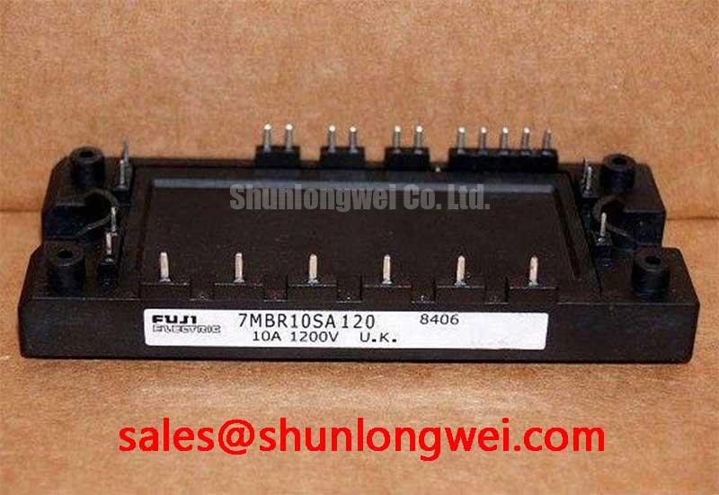
Precision stepper and brushless DC (BLDC) motor servo actuators demand thermal repeatability across continuous acceleration and braking cycles. The Fuji Electric 7MBR10SA120 integrates a three-phase input rectifier, a dynamic brake chopper, a three-phase inverter bridge, and an onboard NTC thermistor into a compact Power Integrated Module (PIM) housing. The module features an official rating of VCES = 1200V and a continuous collector current rating of IC = 10A at a case temperature of 80°C (Official Datasheet Specification). Because total maximum power dissipation is bounded at Ptot = 80W per IGBT element (Official Datasheet Specification), structural mounting precision determines whether the junction temperature remains safely within rated margins or drifts into thermal runaway.
Baseplate flatness and convexity compensation require strict control over thermal interface material (TIM) deposition. When installing the module onto a milled aluminum or copper heatsink, surface roughness must be held to Rz ≤ 10 µm with a total flatness tolerance within 50 µm across the mounting span (Design Consideration based on standard industrial heatsink practices). Apply a uniform layer of high-conductivity thermal grease using a calibrated metal stencil or roller to achieve a wet thickness between 50 µm and 100 µm (Typical Starting Point for standard silicone-based compound application). Excessive paste thickness increases conductive thermal resistance, whereas insufficient volume creates air voids near the internal NTC thermistor and power dies.
⚠️ Field Alert: Uneven screw torque distorts the ceramic direct copper bonded (DCB) substrate inside the module. Always secure the mounting screws progressively in a crosswise pattern. Pre-tighten all screws to approximately 1.0 N·m (Design Consideration), followed by a final tightening pass to the manufacturer-specified mounting torque. Allow 30 minutes for TIM relaxation and settling before performing thermal calibration under load.
| Parameter | Official Datasheet Value | Field Maintenance & Operational Impact |
|---|---|---|
| Collector-Emitter Voltage (VCES) | 1200V | Provides necessary headroom for 400V/480V industrial grid variations. |
| Continuous Inverter Current (IC) | 10A (at TC = 80°C) | Matches low-to-medium power robotic joints and precise BLDC servo axes. |
| Saturation Voltage (VCE(sat)) | 2.1V (Typical at 10A, 25°C) | Sets baseline conduction loss inside tightly sealed motion control cabinets. |
| Maximum Power Dissipation (Ptot) | 80W (per IGBT element) | Requires thermal impedance checks during preventative maintenance. |
| Integrated Topology | Rectifier + Brake + Inverter + NTC | Eliminates parasitic interconnect inductance between discrete functional stages. |
Multi-Module Parallel Current Sharing & Positive Tempco Dynamic Balancing
In high-torque multi-axis actuator stages or distributed motion arrays requiring current scaling, engineers occasionally parallel discrete converter channels. The IGBT dies within the 7MBR10SA120 display a positive temperature coefficient of saturation voltage at elevated junction temperatures (with typical VCE(sat) rising alongside Tj as indicated in the factory data tables). This characteristic natively aids static current balancing across parallel branches because a hotter branch experiences increased dynamic on-state resistance, redirecting excess steady-state current into cooler parallel channels.
Static balancing alone does not resolve dynamic switching imbalances caused by asymmetric stray inductances. Loop inductances within gate circuits and DC-bus connections can shift the turn-on and turn-off transitions between paralleled dies. Incorporating a low-inductance connection topology, such as that detailed in technical analyses on Laminated Busbar Low-Inductance DC-Link Distribution in Inverters, reduces parasitic loop inductance and dampens destructive transient overshoots during high di/dt switching transitions.
When upgrading legacy equipment or configuring alternate sub-assemblies, maintenance technicians frequently compare topology footprints. For legacy systems lacking integrated input rectifiers or requiring dedicated six-pack switching without an internal brake switch, technicians often evaluate the standalone 6MBI10S-120 six-pack module. Conversely, in centralized DC bus architectures where high-capacity external rectification feeds multiple small servo drives, auxiliary building blocks such as the 2MBI150-060 dual-pack switch are utilized to manage main distribution buses.
For system-level current sharing across distinct inverter units operating in a shared microgrid or motion bus, engineers employ frequency and voltage droop compensation strategies, drawing on concepts established in Droop Control for Parallel Inverter Operation in AC Microgrids to synchronize load sharing across independent control loops without mutual cross-conduction.
Cosmic Ray Robustness: Voltage Derating Curves across 2000m-4000m Altitudes
Industrial motion systems deployed at high altitudes encounter elevated terrestrial cosmic neutron flux. At altitudes exceeding 2000 meters, atmospheric shielding decreases, leading to a higher probability of Single Event Burnout (SEB) failures in power semiconductors biased near their breakdown ratings. When applying the 1200V-rated 7MBR10SA120 in continuous duty cycles at elevated altitudes, continuous DC-bus voltage derating serves as a vital safeguard.
⚠️ Maintenance Note: Standard sea-level installations operate on DC bus levels between 540V and 680V (rectified 400V/480V line). For installations between 2000m and 4000m above sea level, operating the continuous DC link below 600V (Design Consideration based on standard altitude derating guidelines for 1200V class silicon) dramatically suppresses cosmic ray SEB failure rates. Furthermore, clearance and creepage distances across terminal pins must be scaled up to prevent atmospheric flashover in low-pressure, thin-air environments.
Preventative maintenance schedules at high-altitude manufacturing sites must also track line voltage spikes resulting from regenerative braking. When decelerating inertial servo loads, kinetic energy pumps back into the DC-link capacitors. The internal brake chopper IGBT within the 7MBR10SA120 must be engaged via an external braking resistor sized to absorb peak surges, preventing the DC bus from exceeding the cosmic-ray-safe voltage envelope. Detailed failure diagnosis techniques and dielectric test procedures are available in the Field Engineer’s Handbook for deep-dive field analysis.
Negative Gate Bias vs Active Miller Clamping in Fast-Switching Half-Bridges
Precision BLDC servo drives switch at higher frequencies (typically 10 kHz to 20 kHz) to achieve low acoustic noise and smooth torque ripples. Under these switching rates, high dv/dt transients generated during the turn-on of the complementary IGBT in a half-bridge induce a displacement current through the parasitic Miller capacitance (Cres / Cgc) of the unpowered switch. If this displacement current passes through the gate resistor, it generates an unwanted voltage rise on the gate pin, risking parasitic cross-conduction (shoot-through).
Engineers manage parasitic gate bounce using two primary hardware methods:
- Negative Off-State Gate Bias: Supplying a negative gate bias between -5V and -15V during the off-state holds the gate potential well below the gate threshold voltage (VGE(th)), maintaining a robust noise margin against induced Miller currents.
- Active Miller Clamping: Utilizing a gate driver equipped with an internal or external clamping transistor that pulls the gate to the negative rail or emitter potential through a low-impedance path once the gate voltage falls below approximately 2V during turn-off.
Digital isolators and optocouplers driving the module gate terminals must provide a high Common-Mode Transient Immunity (CMTI) of at least 50 kV/µs to prevent control logic corruption during fast transitions. If active Miller clamping is omitted, engineers often select a dedicated low-value turn-off gate resistor (RG(off)) alongside a symmetrical negative turn-off rail to ensure stable gate hold-down during fast commutation cycles.