


Content last revised on July 4, 2026
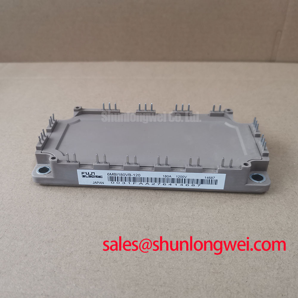
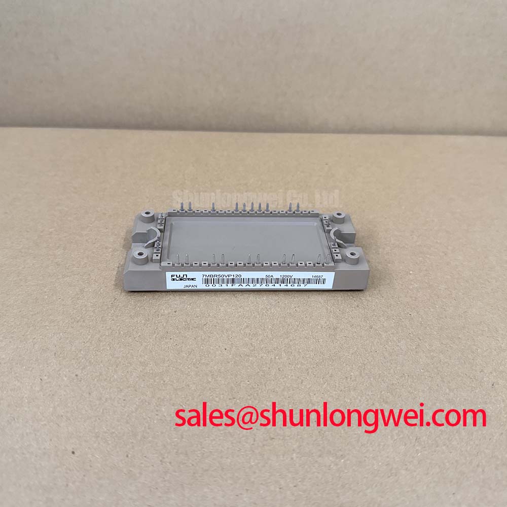
Fuji Electric 7MBR50VP120 IGBT Module: Technical Analysis of the 1200V 50A EconoPIM Design
How can power electronics designers integrate a three-phase rectifier, dynamic brake chopper, and inverter stage into a single package without compromising thermal margin or power density?
The 7MBR50VP120 EconoPIM module optimizes space-constrained industrial motor control systems by integrating three complete power stages into a single, low-profile footprint. Operating at a rating of 1200V and 50A, it features an inverter thermal resistance Rth(j-c) of 0.54°C/W. This compact design reduces component count and simplifies PCB layout routing while minimizing overall engineering time. To resolve parasitic turn-on issues under high dV/dt, this module's gate-emitter threshold characteristics support stable off-state voltage without complex driver clamping.
Frequently Asked Questions
Solving Integration Challenges and Parameter Anomalies
How does the junction-to-case thermal resistance Rth(j-c) of 0.54 °C/W affect thermal management and heatsink selection?
The low thermal resistance of 0.54 °C/W permits efficient heat transfer, allowing designers to minimize heatsink size while keeping junction temperatures below the 150°C operating limit.
What is the impact of VCE(sat) scaling up to 2.50V at 125°C on system conduction losses?
As temperature rises, VCE(sat) increases from 2.15V to 2.50V, representing a positive temperature coefficient that assists in safe paralleling but requires dynamic loss modeling at high temperatures.
Key Parameter Overview
Decoding the Specifications for Enhanced Thermal Design
The collector-emitter saturation voltage VCE(sat) can be likened to the pressure drop across a water valve; a lower drop means less energy is lost as heat while the valve is open. For a comprehensive overview of selection criteria, consult our power semiconductor selection guide.
| Functional Group | Parameter Symbol | Key Specifications (Typical / Max) | Engineering Context |
|---|---|---|---|
| Inverter (IGBT & FWD) | VCES | 1200V (Max) | Blocking voltage headroom for 400V AC grid operations. |
| IC | 50A (Continuous at Tc=80°C) | Continuous output current capability. | |
| VCE(sat) (terminal) | 2.15V (Typ) / 2.60V (Max) at Tj=25°C | Conduction loss metric under rated current. | |
| Converter (Diode) | VRRM | 1600V (Max) | Reverse blocking voltage for rectifier bridge. |
| IO | 50A (Continuous) | Rectified output current handling. | |
| Brake (IGBT) | VCES | 1200V (Max) | Voltage limit for dynamic braking stage. |
| IC | 35A (Continuous) | Brake chopper power capacity. | |
| Thermal & Isolation | Rth(j-c) | 0.54 °C/W (IGBT) / 0.91 °C/W (Diode) | Junction-to-case thermal resistance. |
| Visol | 2500V AC (1 minute) | Electrical isolation rating for chassis safety. |
Download the 7MBR50VP120 datasheet for detailed specifications and performance curves.
Technical & Design Deep Dive
Unpacking the Physics of Trench Gate Technology and Gate Control
The 7MBR50VP120 leverages Fuji Electric's proprietary V-Series trench gate technology, which improves the trade-off between switching speed and conduction loss. Traditional planar IGBTs struggle with high saturation voltages, but the trench architecture provides a vertical channel that increases carrier concentration, driving down VCE(sat) to 2.15V. This ensures that the module runs cooler even when operating at elevated switching frequencies. To learn more about package architectures, explore the ultimate guide to IGBT modules.
Thermal management is optimized through a thin ceramic DBC substrate. Understanding why thermal resistance Rth matters is crucial when designing the interface to the external heatsink. The inverter IGBT's low Rth(j-c) of 0.54 °C/W maintains junction temperatures well within the operational limit, preventing thermal runaway. To manage parasitic voltage spikes, designers must minimize PCB trace loops, as stray inductance in the DC-link busbar can cause transient overvoltages exceeding the 1200V rating during turn-off phases.
Additionally, the integrated dynamic brake IGBT acts like a relief valve in a pneumatic circuit, discharging excess regenerative energy safely when the motor decelerates. By shunting power through an external braking resistor, it shields the DC-link capacitors from overvoltage. The integrated NTC thermistor sits directly on the substrate, supplying immediate thermal feedback to the external gate driver to trigger overtemperature protection routines before irreversible damage occurs.
To summarize gate control metrics: What is the primary benefit of the trench gate structure? It minimizes conduction losses by reducing collector-emitter saturation voltage. How does the integrated thermistor protect the module? It provides real-time internal temperature monitoring to prevent overtemperature failures.
Application Scenarios & Value
High-Fidelity Analysis of Motor Drives and Servo Converters
For 400V AC motor drives demanding integrated braking and compact layout, this 1200V 50A module is the optimal choice.
Consider a high-capacity conveyor belt driven by a 15kW motor. During startup, the motor draws a large surge current that places severe stress on the inverter stage. The 7MBR50VP120 manages this with its 100A pulse current capability and transient thermal capacity, ensuring smooth acceleration without triggering overcurrent trips. When the conveyor stops, the integrated brake stage handles the regenerative energy, returning safety and stability to the grid interface while adhering to the IEC 61800-3 EMC standard.
For systems requiring different capacity or configurations, alternatives such as the 7MBR50VP120-50 offer identical electrical specs with alternative lead options, while the 7MBR75VB120-50 provides higher current handling of 75A, and the older 7MBR50SB120 serves legacy drive architectures. To verify compatibility with your existing mechanical outline, or to query current availability, contact our technical sales team for comprehensive support.