Content last revised on September 10, 2026
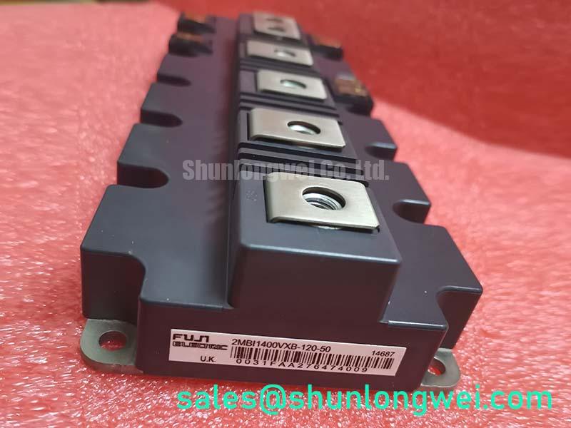
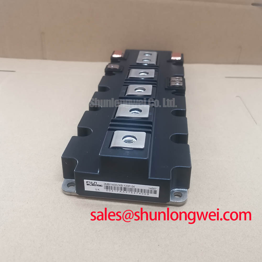
Fuji Electric 2MBI1400VXB-120P-50 IGBT Module: Thermal Optimization for Extreme Power Applications
This module delivers exceptional thermal dissipation through an ultra-low thermal resistance, ensuring robust switching reliability in high-current industrial converters. Utilizing Fuji Electric's advanced technology, this dual-channel power stage offers a breakdown rating of 1200V and a continuous current capacity of 1400A, supported by a junction-to-case thermal resistance of 0.0195 °C/W. Designed to fit high-power density profiles, it minimizes junction temperatures under heavy cyclic loads and optimizes drive space with low-inductance packaging. Engineers looking to replace discrete setups often ask how a single package handles transient overcurrent. By integrating dual-switch topology rated for a peak collector current of 2800A, it eliminates unbalanced parallel paths. For 1200V motor drives requiring maximum thermal margin under continuous 1400A load, this module is the optimal choice.
Key Parameter Overview
System-Level Parameters Organized by Functional Groups
Before integrating this module into a system, developers need to reference its electrical ratings. The tables below group the electrical and thermal limits from the official documentation to assist in your preliminary simulation studies.
| Functional Group | Specification Parameter | Symbol | Typical / Max Value |
|---|---|---|---|
| Absolute Maximum Ratings (Tc = 25°C) | Collector-Emitter Voltage | VCES | 1200V |
| Continuous Collector Current (Tc = 100°C) | IC | 1400A | |
| Collector Power Dissipation (Per Device) | PC | 7650W | |
| Electrical Characteristics (Tj = 25°C) | Collector-Emitter Saturation Voltage (Terminal) | VCE(sat) | 1.75V (Typ) |
| Gate-Emitter Threshold Voltage | VGE(th) | 6.5V (Typ) | |
| Internal Gate Resistance | Rg(int) | 0.79 Ω (Typ) | |
| Thermal & Insulation Limits | Thermal Resistance (Junction-to-Case, IGBT) | Rth(j-c) | 0.0195 °C/W (Max) |
| Isolation Voltage (AC, 1 minute) | Viso | 4000VAC |
Download the 2MBI1400VXB-120P-50 datasheet for detailed specifications and performance curves.
Application Scenarios & Value
Achieving Thermal Reliability and High-Power Integration in Industrial Environments
High-power systems such as industrial motor drives, large-scale uninterruptible power supplies (UPS), and induction welding machines require reliable switching switches that can handle thousands of amperes without localized hot spots. In industrial cranes or conveyor control networks, transient load hoists generate large starting current surges. Standard system designs often use paralleled discrete components to share this load, but layout imbalances can cause unequal current sharing, causing thermal runaways.
The 2MBI1400VXB-120P-50 solves this challenge by packing a complete half-bridge leg into a low-inductance package, rated for a pulse current limit of 2800A. Utilizing this module eliminates the physical layout parasitics of separate switches, simplifying electromagnetic compatibility (EMC) compliance. For designers working on line-voltage selection, reviewing a power semiconductor selection guide is recommended. For systems requiring higher operational voltages, the related 2MBI1400VXB-170E-50 offers a VCES of 1700V, whereas designs requiring a more compact envelope can evaluate the 2MBI900VXA-120P-50.
Technical & Design Deep Dive
Thermal Transfer Physics and Parasitic Mitigation Strategies
To understand how this module handles 1400A, engineers must look at its thermal management and package parasitics. The junction-to-case thermal resistance (Rth(j-c)) of 0.0195 °C/W acts like an extremely wide, clear highway for heat escape, preventing thermal traffic jams at the silicon junction. Even under maximum collector power dissipation of 7650W, this low resistance ensures that heat is quickly drawn away to the heatsink, keeping operating temperatures well below the absolute maximum operating junction temperature limit of 150°C (under switching conditions) or 175°C (under static conditions). When calculating thermal budgets, engineers can find useful testing advice in our guide to decoding IGBT datasheets.
Switching high currents at rapid speeds creates high di/dt rates, which react with package stray inductances (Ls) to produce voltage spikes. The 2MBI1400VXB-120P-50 uses a low-inductance terminal structure that keeps the package loop inductance minimized. The internal gate resistance Rg(int) of 0.79 Ω works like a shock absorber in a vehicle suspension, damping parasitic oscillations to secure switching transitions without forcing high external gate resistor values. This structural design helps developers limit turn-on and turn-off surges, preventing damage to the 1200V rated oxide layer.
What is the primary benefit of the low-inductance structure? It reduces voltage spikes during high di/dt switching. What is the continuous current rating at 100°C case temperature? The continuous current rating is 1400A.
Frequently Asked Questions
Direct Answers to Critical Engineering Inquiries
How does the Rth(j-c) rating of 0.0195 °C/W affect thermal safety margins and heatsink sizing?
The thermal resistance of 0.0195 °C/W limits the temperature rise between the silicon junction and the copper base plate. For instance, at 1000W of continuous power loss, the junction temperature rises only 19.5°C above the base plate temperature. This allows systems to use smaller liquid-cooled or forced-air heatsinks while maintaining a safe operating margin below the maximum operating junction temperature limit of 150°C.
What gate voltage range is required to drive this module, and how does VGE(th) affect turn-on stability?
The recommended gate-emitter drive voltage is +15V for the turn-on state and -15V for the turn-off state. The gate-emitter threshold voltage VGE(th) has a typical value of 6.5V. This threshold level prevents accidental turn-on caused by transient noise or Miller-effect currents in the gate loop, protecting the half-bridge from shoot-through failures.
Can the 2MBI1400VXB-120P-50 module run continuously at 1800A in typical industrial conditions?
No, the continuous collector current limit of 1800A is rated under a controlled case temperature of 25°C. In typical industrial environments, the case temperature easily reaches 100°C, which limits the continuous operating current to 1400A. Standard engineering practices require de-rating based on actual heatsink performance and ambient temperatures.
For engineering teams working on high-power inverter prototypes or industrial drive retrofits, verifying thermal limits under actual operating loads is essential. Contact our technical sales department to check stock levels, verify package outlines, or request spec sheets for your project design phase.