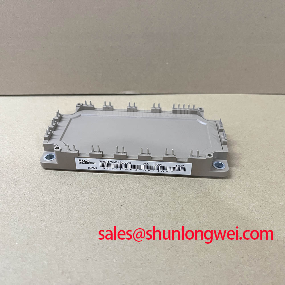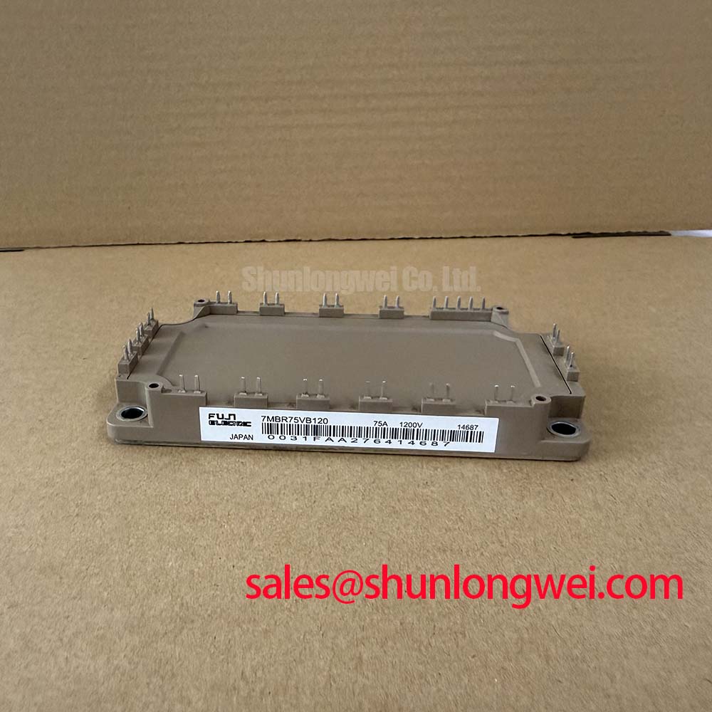


Content last revised on September 27, 2026
7MBR75VB120 Operational Boundaries: Gate-Drive Isolation and Insulation Limits
With the DC bus discharged, compare the cold resistance and diode-test polarity of the 7MBR75VB120 terminals against the equipment schematic before connecting a gate driver. The supplied factory ratings identify this Fuji Electric module as 1200 V and 75 A (Official Specifications). Those ratings establish an initial screening boundary, not a complete replacement decision: terminal assignment, control functions and mounting details still need to match the original equipment documentation.
At incoming inspection, identify each power and control terminal from the applicable Fuji Electric drawing before measuring between them. A diode-test reading is useful for comparing corresponding paths with a documented, known-good unit, but it does not establish a gate-drive isolation rating. Record the meter polarity and reading for each path so that a later comparison uses the same conditions.
Galvanic isolation, reinforced insulation and common-mode transient immunity are properties to verify for the complete drive arrangement, including its supply, signal interface, board layout and required clearances. They cannot be assigned to this module from its voltage and current ratings. As a Design Consideration, inspect isolation boundaries on the drive board for contamination or damage, then evaluate unwanted gate pulses during representative switching tests. Set clearance and withstand requirements from the equipment’s applicable insulation design and component documentation rather than assuming a universal voltage threshold. Fuji Electric’s Power Semiconductor and IPM Modules information provides manufacturer context; the exact module drawing and specifications remain necessary for terminal-level checks.
💡 Bench Tip: Keep the gate terminals protected from electrostatic discharge and compare cold diode-test readings only with the DC bus discharged and the same meter polarity used on the reference unit.
7MBR75VB120 Operational Boundaries: Evaluating Gate-Emitter Loop Routing
Trace the installed gate-drive return to the terminal designated by the original module documentation. If that documentation identifies a separate auxiliary emitter connection, assess whether the drive return uses it rather than a high-current busbar path; do not infer that such a terminal exists from the 7MBR75VB120 model name alone. This is a Design Consideration because shared power-path inductance can disturb the voltage seen by a gate driver during switching.
Keep the gate and its documented return path close together in the replacement assembly, then examine the gate waveform under the equipment’s intended operating conditions. Ringing or an unexpected turn-on pulse warrants a comparison with the known-good drive path, including connector contact, routing and driver supply behavior. A static meter check cannot determine switching stability.
If the equipment uses desaturation protection, verify its blanking interval, fault response and turn-off behavior against the driver design and the module’s applicable short-circuit limits. Neither a detection time nor a two-stage soft turn-off function is established by the supplied 1200 V and 75 A ratings. The system engineer should confirm those settings with controlled fault testing appropriate to the equipment, not transfer timing assumptions from another module.
Transient Dynamics & Electrical Design: Derating and Compatibility Checks for 7MBR75VB120
The 1200 V voltage rating and 75 A current rating are Official Specifications, but they do not, by themselves, define permissible switching frequency, case temperature or cooling capacity. For an industrial inverter welder or medium-frequency induction heating supply, first compare the original schematic, terminal map, drive requirements and thermal interface with the proposed installation. These are compatibility evaluations, not claims that the module was specified for either machine.
As a Design Consideration, minimize the commutation loop formed by the DC-link capacitors, bus connections and switching devices. Stray inductance can raise the turn-off voltage above the steady DC-link level; measure the peak at the relevant terminals during switching and assess it against the module rating. If the equipment has a bootstrap gate supply, check its voltage through the actual operating sequence and review the charging diode’s recovery behavior. Bootstrap suitability depends on that sequence and the driver circuit, not on the module’s current rating.
Do not assume that parallel devices will share current because they carry the same part number. Static sharing depends on measured conduction characteristics and temperature; dynamic sharing also depends on matched gate paths and commutation layout. For thermal assembly, examine the baseplate and heatsink contact surfaces, apply the interface material according to the equipment procedure, and use the specified mounting sequence and torque from the applicable drawing. An unverified paste thickness or fastener torque would not be an Official Specification for this module.
When comparing another part, such as 6MBI100S-140, evaluate its terminal arrangement, control method, electrical limits and mounting interface independently. A different rating or model family does not establish drop-in compatibility.
Preventing Spurious Faults: Regenerative DC-Bus Voltage Surge Guidelines for 7MBR75VB120
When a drive reports an overvoltage fault, capture the DC-link waveform and the module’s switching waveform before attributing the event to the 7MBR75VB120. A rising bus during motor deceleration points the investigation toward the system’s regenerative-energy path; a sharp peak at turn-off calls for examination of commutation-loop inductance, snubbing and measurement technique. Those observations can coexist, so one alarm code is not a component diagnosis.
If the equipment includes a braking switch and resistor, confirm their presence and ratings from its schematic. The supplied module specifications do not establish an internal braking IGBT or define resistor sizing. A Design Consideration is to evaluate the braking path against the equipment’s deceleration duty and measured DC-link behavior. Where a metal-oxide varistor or another surge absorber is fitted, check its location and condition against the original design; it should not be treated as a substitute for controlling repetitive switching overshoot.
For an inverter driving a motor through a long cable, inspect the voltage at the drive output and at the motor terminals under suitable test conditions. Cable reflections can produce a motor-terminal peak that a DC-link measurement misses. Filter selection belongs to the equipment design and should follow measured waveforms and motor insulation requirements. For related checks on gate drive, bus layout and heat removal, see IGBT Design & Integration.