Content last revised on July 4, 2026
Fuji Electric 7MBR75VP060A-50 IGBT Module Analysis
How can design engineers reduce parasitic inductance and PCB footprint in three-phase motor drives without compromising switching losses?
For space-constrained 600V drives demanding low conduction loss, this 75A PIM module is the optimal choice.
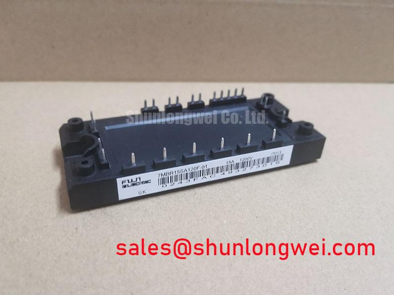
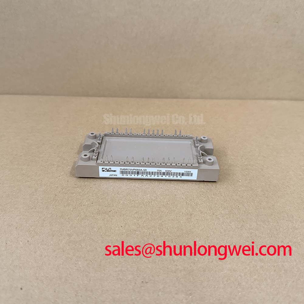
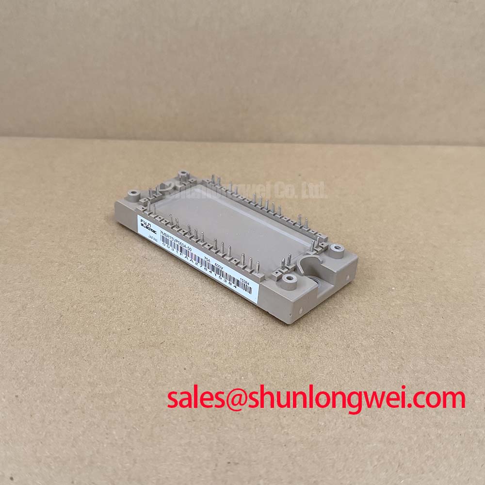
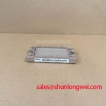
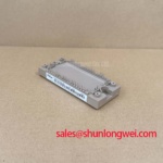
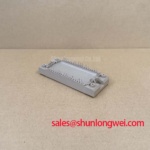
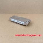
The Fuji Electric 7MBR75VP060A-50 integrates a converter bridge, brake chopper, and six-pack inverter into an M719 package. Featuring ratings of 600V and 75A, this V-series module achieves a typical collector-emitter saturation voltage (VCE(sat)) of 1.90V. It helps reduce stray inductance, improves power density, and simplifies thermal management in industrial systems.
Frequently Asked Questions
Resolving Critical Gate Drive and Thermal Resistance Engineering Inquiries
-
What is the primary benefit of the integrated PIM design?
It reduces stray inductance and saves PCB area. -
What role does the NTC thermistor play?
It provides real-time case temperature monitoring for safety. -
How does the low terminal VCE(sat) of 1.90V impact system cooling requirements?
It reduces conduction losses, allowing smaller heatsinks and higher power density. -
What gate drive voltage is recommended to prevent dynamic turn-on failures in this module?
Operating at +15V gate bias ensures full saturation, while negative gate voltage prevents noise-induced parasitic turn-on.
Key Parameter Overview
Highlighting Key Parameters for Loss and Thermal Calculations
| Parameter | Conditions / Sections | Standard Specification | Design Importance |
|---|---|---|---|
| Collector-Emitter Voltage (VCES) | Inverter Section, Tj = 25°C | 600V | Maximum voltage limit for 400V DC bus applications |
| Continuous Collector Current (IC) | Inverter Section, Tc = 80°C | 75A | Determines continuous motor drive current capacity |
| Collector-Emitter Saturation Voltage (VCE(sat)) | Terminal, IC = 75A, VGE = 15V, Tj = 25°C | 1.90V (Typ) | Directly correlates to conduction losses in the inverter |
| Maximum Junction Temperature (Tj) | Inverter and Brake IGBTs | 175°C | Defines upper thermal limits during heavy transient overloads |
| Isolation Voltage (VISO) | AC, 1 minute duration | 2500 VAC | Provides high functional isolation for system safety |
| Thermal Resistance (Rth(j-c)) | Inverter IGBT (per device) | 0.50 °C/W (Max) | Crucial parameter for junction-to-case heat flow efficiency |
Download the 7MBR75VP060A-50 datasheet for detailed specifications and performance curves.
Technical Deep Dive
Switching Efficiency and Saturation Voltage Trade-off in 6th-Gen V-Series Silicon
The core design philosophy of the 7MBR75VP060A-50 focuses on optimizing the trade-off between conduction and switching losses. Using the Fuji Electric V-Series IGBT technology, the chip layout is engineered to lower carrier injection. This reduces switching times while keeping the saturation voltage low. For engineers engaged in understanding IGBT modules, balancing conduction loss with high-frequency performance is key to maintaining system reliability.
The collector-emitter saturation voltage (VCE(sat)) of 1.90V at 75A represents the conduction efficiency of the module. VCE(sat) acts like a narrow valve in a water pipe. A narrower valve creates more resistance, generating excess heat. By maintaining a low saturation voltage, the 7MBR75VP060A-50 works like a wider valve, allowing current to flow with minimal voltage drop and lower overall power loss.
In high-frequency designs, switching losses (Eon and Eoff) are dominant. The V-series trench gate structure minimizes gate charge, accelerating transitions. When decoding IGBT datasheets, note the turn-on time of 0.36 µs and turn-off time of 0.52 µs. Fast transitions ensure the module spends less time in the active region, reducing the energy dissipated per cycle.
However, fast switching can generate severe voltage overshoots due to parasitic inductance. The integrated PIM layout of the 7MBR75VP060A-50 mitigates this by keeping terminal-to-chip connection paths as short as possible. This layout reduces internal loop inductance, allowing faster switching speeds without generating destructive dV/dt rates that could exceed the safe operating limits of the silicon.
Application Scenarios & Value
System-Level Efficiency in Harsh Space-Constrained Motor Controls
The industrial 7MBR75VP060A-50 is designed for power conversion stages in compact industrial equipment. Modern engineers frequently face the challenge of designing closed-loop servo drives that operate within compact, sealed enclosures. In these fan-less designs, heat accumulation is a critical failure driver. The module's low thermal resistance (Rth(j-c)) of 0.50 °C/W for the inverter IGBT enables efficient heat dissipation directly to the external chassis.
Consider a conveyor system driven by a 600V, 75A Variable Frequency Drive (VFD). During startup, the system experiences high motor surge currents. The 7MBR75VP060A-50 handles these startup transients safely due to its robust short-circuit withstand capability and maximum junction temperature of 175°C. This temperature margin acts like the redline on an engine tachometer; while you want to operate below it, having a high headroom ensures that occasional transient peaks do not lead to catastrophic thermal runaway.
For design validation and maintenance, engineers can follow standard procedures for testing IGBT modules using a multimeter to verify diode front-to-back ratios and gate isolation. This helps ensure that the module operates safely within EMC limits defined by the IEC 61800-3 standard.
While the 7MBR75VP060A-50 is suitable for 75A applications, designs requiring higher current capacity can utilize the 7MBR100VP060-50 for 100A continuous operation. For alternative package options, the related 7MBR75VP060-50 offers functional equivalence.
From a strategic perspective, integrating the 7MBR75VP060A-50 into industrial motor drive systems aligns with modern energy efficiency standards. By reducing the overall component count and maximizing thermal margin, OEMs can build robust, high-density systems that lower the total cost of ownership and meet stringent eco-design regulations.