

Content last revised on September 22, 2026
Benchtop Waveform Tuning: Mitigating Stress via Type-2 Coordination: Sub-Cycle Dead-Short on B612F-2T
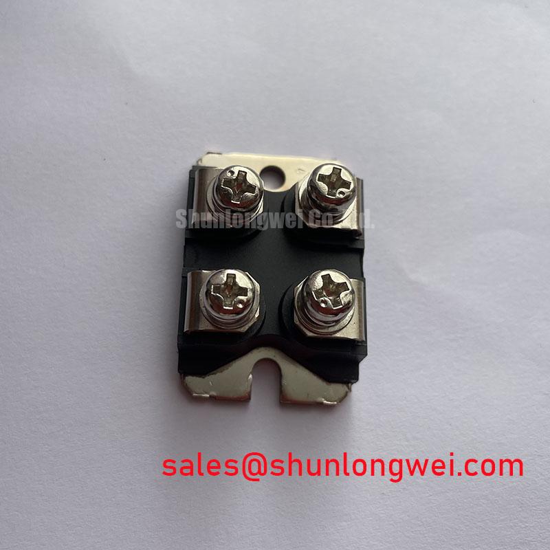
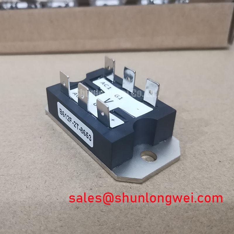
Before connecting the device to a live control cabinet, verify the marking, inspect the module housing, and confirm that the circuit position is rated for 600.0 V and 5.0 A. The Crydom B612F-2T is identified from the supplied product data as a Thyristor/Diode Module in a Module package. These are the confirmed product parameters available for this listing; gate thresholds, surge current, thermal resistance, isolation rating, I²t withstand, terminal arrangement, and mounting torque require verification against the applicable manufacturer documentation before commissioning.
| Parameter | Confirmed value | Classification |
|---|---|---|
| Manufacturer | Crydom | Product identification |
| Model | B612F-2T | Product identification |
| Rated voltage | 600.0 V | Official supplied specification |
| Rated current | 5.0 A | Official supplied specification |
| Package | Module | Official supplied specification |
| Product category | Thyristor/Diode Module | Catalog classification |
For equipment repair, the 600.0 V and 5.0 A values should be treated as device-level identification limits rather than a complete system operating prescription. The actual current waveform, duty cycle, ambient temperature, cooling method, line impedance, overload profile, and protective coordination determine whether the module is suitable for a particular installation. A grid-tied static Var compensator or thyristor-switched capacitor assembly should therefore be checked at the circuit level before a replacement decision is finalized.
When evaluating the B612F-2T on a bench, begin with the isolated power stage and confirm the intended terminal connections from the original equipment documentation. Do not infer the internal terminal arrangement from the package appearance alone. A replacement assessment should compare the original module’s circuit symbol, gate wiring, snubber position, fuse location, and heat-spreader interface with the proposed device documentation.
Short-circuit protection requires more than matching the nominal 5.0 A rating. Semiconductor fuse selection normally depends on the prospective fault current, clearing time, fuse I²t characteristic, wiring inductance, repetitive duty, and the semiconductor’s published surge and I²t limits. Those coordination values are not included in the supplied B612F-2T data, so a precise fuse recommendation or guaranteed zero-damage claim cannot be made from the available parameters.
Design Consideration: compare the fuse clearing energy with the applicable thyristor or diode surge withstand data under the real fault waveform, then validate the result with a controlled current-limited test rather than relying on a nominal fuse label. The test engineer should monitor voltage across the module, current through the protected branch, gate reference potential, and the enclosure temperature. Any abnormal ringing may indicate a protection-loop or measurement-loop problem and should be verified against a known-good assembly.
Type-2 coordination is a system protection concept, not a confirmed feature of this individual module. The integrator should obtain the relevant Crydom switching, surge, thermal, and protection specifications before approving the B612F-2T for a capacitor-switching branch. The same review applies to a static Var compensator, where repetitive switching and capacitor inrush can impose stresses that are not represented by a simple steady-state current value.
B612F-2T Thermal-Electrical Optimization: Saturable Reactor and Snubber Sizing to Practical Tuning
In a thyristor-switched capacitor stage, the snubber and any series reactor influence voltage slew, current rise, ringing, and conducted interference. Their values cannot be prescribed from the confirmed 600.0 V and 5.0 A ratings alone. Designers should first capture the actual switching waveform with suitable differential voltage and current probes, then evaluate the peak voltage, current rise, ringing frequency, and repetition rate under the intended line and load conditions.
RC snubber selection is a Design Consideration. The resistor must tolerate the transient energy and repetitive dissipation, while the capacitor requires an appropriate voltage, pulse, and safety classification for its position in the circuit. The final values should be determined from measured switching behavior and verified against the component manufacturer’s allowable operating conditions. A snubber that is too small may provide limited damping; one that is too large can increase reactive current and resistor heating.
A saturable reactor may be evaluated where the system requires control of the initial current rise or capacitor inrush. Its suitability depends on core behavior, reset conditions, line frequency, fault current, temperature, and the repetitive switching pattern. These are system-level design variables, not published B612F-2T specifications. The engineer should validate the reactor and snubber together because changing one can alter the voltage stress and current waveform seen by the other.
Thermal inspection should include the module mounting surface, thermal interface condition, heat sink cleanliness, airflow direction, and the tightness of the power terminals. The actual junction temperature must be evaluated using the applicable thermal resistance and transient thermal impedance data from the manufacturer. That information is not present in the supplied product parameters, so a numerical junction-temperature margin should not be assigned here.
⚠️ Maintenance Note: Monitor contact temperature during scheduled service and verify the heat-sink air path after cleaning, because dust buildup or a deteriorated thermal interface can change the operating temperature without changing the electrical rating.
For a neutral comparison during service planning, engineers may review the mechanically different SKKH330/08E alongside the B612F-2T. This is not a recommendation or an assurance of interchangeability. Voltage, current, topology, terminal layout, gate requirements, thermal interface, and protection coordination must all be checked against the original assembly.
B612F-2T Operational Boundaries: Evaluating Minimizing Commutation Turn-Off Voltage Limits
Commutation behavior should be assessed from measured voltage and current waveforms rather than assumed from the product category. Reverse-recovery current, recovery time, soft-recovery behavior, dv/dt capability, di/dt capability, latching current, holding current, gate trigger current, and gate trigger voltage are not confirmed in the supplied B612F-2T parameter set. They must be taken from the applicable technical documentation before being used in a design calculation.
For a grid-tied static Var compensator, the engineer should inspect the turn-off transition at the operating line voltage, capacitor condition, and switching angle used by the controller. Probe placement is important: long probe leads can add ringing and common-mode pickup that may be mistaken for semiconductor stress. Use a measurement arrangement appropriate for the voltage category and compare the waveform with a known-good module position when available.
Gate triggering also deserves a separate review. A controller may use a pulse train or a single trigger pulse, but the correct choice depends on the thyristor’s published gate requirements, pulse width, isolation method, and the timing strategy of the complete switching assembly. The B612F-2T supplied data does not state IGT or VGT, so no trigger-current or trigger-voltage value should be assumed. The system integrator should verify those values from the original device documentation before modifying the gate circuit.
Gate-loop parasitic inductance can contribute to ringing and common-mode ground bounce. A practical Design Consideration is to keep the gate return physically associated with its intended reference path, separate high-current commutation paths from sensitive trigger wiring, and validate the result with an isolated oscilloscope measurement. If negative gate bias is being considered for turn-off control, its voltage, timing, isolation, and compatibility must be confirmed by the applicable gate-drive specification rather than selected as a generic field setting.
The same caution applies to claims about electromagnetic compatibility, high-altitude operation, cosmic-ray effects, single-event burnout, insulation reliability, or long-term field failure rates. No such numerical reliability or compliance data is included in the supplied B612F-2T information. The module itself should not be described as independently certified for complete-equipment EMC performance. System-level verification remains the responsibility of the equipment designer.
For background on closed-loop behavior and frequency-domain assessment, engineers can consult Transfer Function and Loop Gain Bode Analysis in Switch-Mode Regulators. This reference does not provide B612F-2T limits; it is only a general explanation of system analysis methods. Likewise, an industrial sensor network reference such as IO-Link Open Communications Protocol for Industrial Sensors and Actuators should not be treated as evidence that this power module contains an IO-Link interface.
Benchtop Waveform Tuning: Mitigating Stress via Harmonic Current Injection and Line Filter on B612F-2T
When the B612F-2T is considered for a thyristor-switched capacitor branch, firing-angle tests should be performed with current limiting, appropriate isolation, and a defined measurement plan. The intended firing range, including any controller command equivalent to a low or high firing angle, should be checked against the original control architecture. The supplied product information does not specify an alpha range, power-factor curve, reactive-power capability, harmonic spectrum, or line-filter requirement.
At each operating point, record line voltage, branch current, trigger timing, capacitor voltage, commutation behavior, and temperature. Compare the current waveform with the expected system topology rather than assigning a fixed power-factor result to the module. Harmonic current injection can be affected by source impedance, transformer leakage, capacitor tolerance, filter resonance, control timing, and other switched branches. These conditions may produce different results in two installations using the same semiconductor module.
A line filter should be selected only after the disturbance spectrum and source impedance have been measured or calculated by the system designer. Filter resonance must be assessed with the complete network, including the SVC bus, transformer, capacitor bank, reactor, protective fuse, and switching device. The filter cannot be sized from the B612F-2T’s 600.0 V and 5.0 A ratings alone.
During maintenance, inspect terminal condition, heat-spreader contact, enclosure condensation, and airflow before interpreting waveform changes as a semiconductor fault. Moisture and contamination can affect insulation and trigger wiring, while loose power connections can introduce localized heating and intermittent voltage disturbance. Record the original wiring and control timing before replacing the module so that a post-repair waveform comparison remains meaningful.
For broader application context concerning power semiconductor use in industrial energy systems, see the Industrial Applications reference. It is general technical background and does not replace the Crydom documentation required to approve the B612F-2T in a specific SVC or capacitor-switching assembly.