Content last revised on November 9, 2026
BSM150GAR120D Thermal-Electrical Optimization: Floating Gate Bias Supply Decoupling Practical Tuning
With the DC link isolated and its discharge verified, match the BSM150GAR120D terminal markings to the equipment schematic before disconnecting the gate wiring or busbars. Photograph the connections and inspect the mounting surface for contamination, distortion, and uneven contact marks that could complicate replacement.
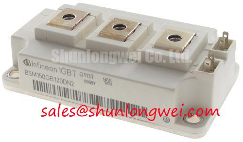
The product specification baseline identifies Manufacturer: Infineon; Part Number: BSM150GAR120D; Collector-Emitter Voltage (Vces): 1200.0 V; Rated Collector Current (Ic): 150.0 A under the specified datasheet conditions; Package: Module; Configuration / Topology: IGBT Power Stage. For replacement assessment, consult the manufacturer datasheet for terminal assignments, rating conditions, dimensions, gate limits, and mounting requirements.
Check the floating driver supply at its local emitter reference while the high-voltage link remains disabled. As a Design Consideration, the auxiliary supply and undervoltage lockout should establish a defined gate-off state before the system permits DC-link energization. Where the equipment uses negative turn-off bias, evaluate that rail against its approved driver schematic rather than assigning a generic negative voltage.
Probe the supply directly at the driver during command transitions. Supply droop, oscillation, or repeated lockout transitions can justify checking local decoupling, connector resistance, and the isolated supply loading. Keep the decoupling return compact without compromising the equipment’s required creepage and clearance. Where bootstrap circuitry is present in the equipment, assess recharge opportunities, capacitor charge balance, and charging-diode recovery against its switching sequence.
Miller-induced gate movement requires attention to the gate return path, driver sink capability, and any existing active clamp. Reverse-transfer capacitance and gate-charge behavior affect this assessment; they are not interchangeable quantities. The Infineon IGBT Modules & Discretes Official Portfolio provides manufacturer context for device technologies, while the exact device and driver documentation govern implementation. Related system devices such as BSM50GD120DN2G require their own circuit and supply checks, not transferred settings.
Pre-Installation Junction Health Check on BSM150GAR120D
Disconnect external paths that could distort the meter reading, then establish terminal identities from the circuit drawing before using diode-check mode. As an Engineering Recommendation, compare readings in both polarities across the main terminals and across any antiparallel diode identified in that drawing. Maintain a controlled gate-emitter state using an appropriate handling procedure; a floating gate can make readings misleading.
Record the meter, polarity, and measurement points rather than treating one forward reading as a universal pass criterion. A persistent low-resistance path or a marked difference from a known-good equivalent warrants further investigation. A handheld meter can screen for gross gate insulation faults, but it cannot establish operating-voltage leakage or switching health.
Inspect terminal barriers, conductor spacing, and busbar alignment before fastening. Connections should sit without forcing the housing or transferring cable strain into terminals. Field Alert: Follow the specified mounting sequence and torque, and apply the approved thermal interface material uniformly rather than using extra compound to compensate for poor contact. The FF150R12KS4 can serve as a comparison reference during sourcing, but replacement acceptance requires matching topology, terminal layout, drive requirements, thermal interfaces, and switching characteristics.
BSM150GAR120D Circuit Protection & Reliability: Thermal Stress in Bidirectional Systems
Separate commanded power direction from the actual semiconductor conduction paths when reviewing regenerative operation. As a Design Consideration, four-quadrant system behavior depends on the complete converter arrangement and control strategy; the module’s voltage and current ratings do not independently establish bidirectional conversion capability.
When evaluating commercial string inverters or micro-grid energy storage equipment, designers should trace battery-to-link and link-to-battery current paths before assessing compatibility. Peak-shaving duty can produce changing conduction and switching losses as current direction, duty cycle, and cooling conditions vary. Compare operating records with heatsink temperature and cooling performance rather than attributing every thermal alarm to the module.
Check heatsink flatness, interface coverage, and the approved fastening sequence during installation. Uneven contact can obstruct heat transfer even when external cooling appears satisfactory. Protection settings should be assessed against the actual sensing location and thermal response. Powering the Digital Backbone offers related converter background; qualification should use the equipment’s applicable load profile and acceptance procedures, not assumed service-life figures.
BSM150GAR120D Operational Boundaries: Evaluating Planar Symmetrical Busbar Geometry
Trace the commutation loop through the local DC-link capacitor, module terminals, and return conductor before changing snubbers. As a Design Consideration, closely coupled outgoing and return paths can reduce loop inductance, provided conductor spacing, insulation, and mechanical support remain appropriate for the equipment.
An Engineering Calculation expresses the first-order turn-off estimate as Vpeak = VDC + Lσ × |di/dt|, linking transient voltage to loop inductance and current slew rate. This estimate excludes ringing and clamp dynamics; measured waveforms must establish the actual peak relative to the 1200.0 V collector-emitter rating and the system’s acceptance limits.
Select snubber capacitance and damping from measured ringing, pulse-energy demand, and component heating rather than a universal inductance target. Use a suitably rated differential probe with a compact connection, then compare terminal overshoot and clamp behavior across the intended operating envelope. Accept the revised busbar arrangement only after checking electrical spacing, joint stability, and switching stress together.