
Content last revised on September 10, 2026
BSM25GB120DN2 Operational Boundaries: Evaluating Long Motor Lead Reflected-Wave Voltage
With the drive fully isolated and the DC link discharged, first inspect the BSM25GB120DN2 terminals, baseplate contact surface, and mounting hardware. Check the relevant terminals for abnormal resistance or short-circuit indications under unpowered conditions, following the equipment manufacturer’s troubleshooting documentation.
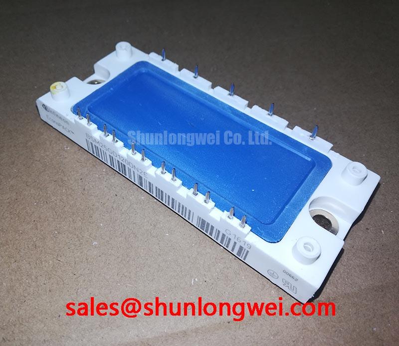
The Infineon BSM25GB120DN2 is a chassis mounted dual IGBT half bridge module with an insulated metal baseplate and integrated NTC thermistor. Its official ratings are 1200 V collector emitter voltage, 38 A continuous collector current at 25°C, and 150°C maximum junction temperature. These values define the device identity; they do not by themselves validate a complete inverter operating condition, gate driver setting, or heatsink capability.
| Parameter | Official Specification |
|---|---|
| Manufacturer | Infineon |
| Module configuration | Half bridge, dual IGBT |
| Collector emitter voltage | 1200 V |
| Continuous collector current at 25°C | 38 A |
| Maximum junction temperature | 150°C |
| Integrated monitoring feature | NTC thermistor |
| Mechanical mounting | Chassis mount with insulated metal baseplate |
For a compact industrial inverter or a high speed CNC spindle drive, inspect the motor cable route before treating a failed module as an isolated power stage event. A long cable behaves as a transmission path during fast switching edges. When the cable impedance and motor terminal impedance are mismatched, reflected voltage can raise the voltage seen at the motor end and alter the waveform returning toward the inverter.
The 1200 V rating is an official datasheet specification for the BSM25GB120DN2. The actual collector emitter peak voltage during commutation remains a system measurement. Designers should capture phase output and DC link waveforms with a correctly rated differential measurement method, using the same cable, motor, and switching conditions that are present in service. A clean low voltage bus test does not automatically represent behavior at production bus voltage or with a loaded spindle.
Design Consideration: output reactors and dv/dt filters can be evaluated where cable reflections, bearing current concerns, motor insulation stress, or ringing are observed. Their suitability depends on the inverter switching behavior, cable length, motor construction, and control requirements. Verify the filter location and grounding method against the machine electrical drawings rather than introducing a filter as a universal repair action.
At the module, examine busbar overlap, DC link capacitor connection distance, phase terminal tightness, and any evidence of heat discoloration near bolted joints. Loose hardware can add resistance and inductance, which can complicate waveform interpretation. ⚠️ Field Alert: Disconnect and verify discharged DC link energy before loosening power connections, then apply mounting and terminal torque only to the equipment manufacturer’s documented fastener specification.
Preventing Spurious Faults: Desaturation Detection Guidelines for BSM25GB120DN2
Desaturation protection belongs to the gate driver system, not to the BSM25GB120DN2 module itself. During a fault investigation, confirm that each IGBT position has a valid gate drive reference, desaturation sensing path, blanking arrangement, fault latch response, and controlled gate discharge path. An unexpected trip can arise from genuine overload, a sensing disturbance, an unsuitable blanking interval, poor driver supply behavior, or common mode noise entering the control reference.
Engineering Recommendation: inspect the desaturation diode, sensing resistor network, gate resistor connections, and driver return path with the power removed before replacing the module. On an energized test bench, compare the suspected channel with a known healthy channel using appropriate isolated instruments. Observe collector emitter behavior, gate emitter behavior, and driver fault output together. A fault flag alone does not establish whether the trigger originated in the IGBT, the load, or the driver board.
For a detected overcurrent event, a controlled soft turn off strategy can reduce the risk of a sharp inductive voltage rise compared with an uncontrolled gate discharge. Its timing and gate current must be validated by the system designer against the actual DC link, commutation inductance, switching waveform, and protection architecture. Gate damping is similarly system determined: excessive resistance can increase switching loss, while insufficient damping can allow ringing and false triggering.
When an installed module must be assessed against another power stage option, the BSM75GD120DLC can be reviewed as a separate device reference. Any substitution decision should verify terminal arrangement, driver compatibility, current requirements, thermal interface, protection thresholds, and the original equipment electrical documentation before installation.
Transient Dynamics & Electrical Design: Thermal Time Constants and Peak Junction on BSM25GB120DN2
The integrated NTC thermistor supports temperature monitoring, but it does not directly report semiconductor junction temperature at every switching instant. The BSM25GB120DN2 has a stated 150°C maximum junction temperature as an official datasheet specification. Under pulsed load, the junction temperature rises faster than the case and heatsink temperatures because heat moves through several thermal paths over different time intervals.
Design Consideration: use the manufacturer thermal impedance information, where available from the applicable datasheet revision, together with measured current waveform, switching behavior, case temperature, and heatsink performance to evaluate peak junction conditions. Multi-section thermal models are useful because they represent the different rates at which heat transfers from the silicon toward the case. The resulting calculation is an engineering calculation, not an independent module guarantee.
In field service, compare NTC behavior, heatsink contact condition, airflow path, fan operation, and thermal compound coverage with a known healthy drive where practical. A rising cabinet temperature, clogged airflow route, uneven clamping, or reduced cooling contact may contribute to repeated thermal alarms or power stage stress. Avoid assigning a single cause from one temperature observation. Verify trends during controlled operation and correlate them with load current and switching activity.
The insulated metal baseplate simplifies chassis mounting while requiring a flat, clean thermal interface. The system integrator should verify the heatsink flatness, fastening sequence, compound application method, and electrical clearances from the original equipment service material. General thermal mounting practice cannot replace the specific mechanical requirements of the installed drive.
BSM25GB120DN2 Circuit Protection & Reliability: Assessing System Insulation Barrier Integrity
Do not infer reinforced isolation capability, insulation test voltage, or common mode transient immunity from the module’s insulated baseplate alone. Documented product information identifies an insulated metal baseplate, while galvanic isolation requirements are determined by the complete inverter construction, including the gate driver, control power supply, PCB spacing, cable routing, enclosure, and applicable equipment standard.
Engineering Recommendation: during repair qualification, inspect the barrier parts in the complete control chain rather than concentrating only on the IGBT module. Check driver isolation devices, power supply isolation, creepage and clearance condition, conformal coating condition where fitted, and earth bonding continuity. Any insulation withstand or common mode immunity requirement should be taken from the original system safety documentation and verified with suitable controlled test equipment.
Spurious gate pulses can be associated with common mode movement and shared return impedance. Keep gate drive loops compact, maintain separation between sensitive driver traces and high energy power conductors, and verify the driver reference path under switching conditions. The required gate off bias, shielding arrangement, and test acceptance criteria are system determined and should be validated against measured peak voltage and gate waveforms.
For broader context on IGBT use across industrial power conversion, see Infineon’s IGBT portfolio and its IGBT modules overview. Application level integration topics are also discussed in this Industrial Applications engineering guide.