
Content last revised on October 6, 2026
BSM400GA120DN2SE3256 Circuit Protection and Reliability: Checking Common-Mode Transients
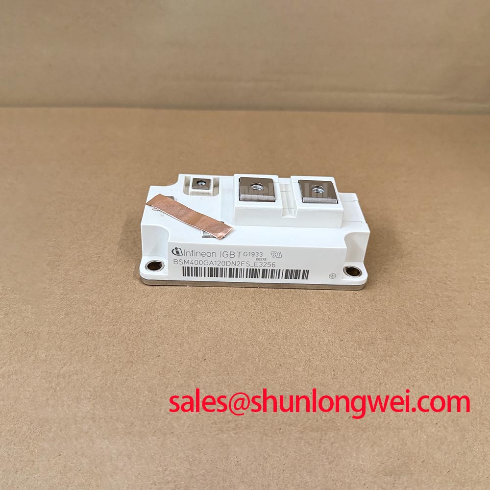
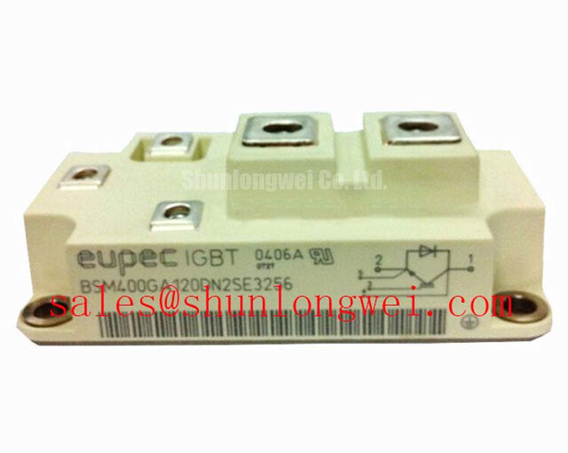
Compare the nameplate rating on the removed power module with the replacement record before measuring its cold terminal impedance. For BSM400GA120DN2SE3256, the supplied official specifications identify an Infineon IGBT module rated at 1200 V and 400 A, with a Module package. Those ratings establish the initial screening boundary; they do not establish terminal layout, mounting dimensions, switching limits, or suitability for a particular converter.
Start at the equipment schematic, not the gate-driver label. Trace the driver supply, isolation boundary, gate and emitter connections, and fault-return path for the position occupied by BSM400GA120DN2SE3256. Common-mode voltage changes during switching can disturb a driver signal or its reference. Whether that disturbance produces an unintended gate pulse depends on the complete driver and layout, not on the module’s 1200 V rating.
Design Consideration: Verify isolation ratings and common-mode transient immunity against the installed driver’s documentation and the converter’s measured switching conditions. A claimed isolation withstand voltage or immunity threshold must not be assigned to this module without its applicable documentation. Inspect board clearances and contamination around the driver barrier, then compare gate-to-emitter waveforms on the suspect position with a known-good position using suitable isolated measurement equipment. A pulse that appears only during an adjacent switch transition calls for checks of the driver return path, coupling paths, and probe setup before attributing the event to the module.
For an installation exposed to condensation risk, inspect enclosure sealing, heater operation where fitted, and deposits around high-voltage terminals during planned shutdowns. These are system-maintenance checks, not an insulation-reliability certification for the IGBT module. If operating altitude or unusual environmental exposure affects the equipment specification, obtain the system designer’s applicable derating assessment; the supplied module ratings alone do not establish a cosmic-ray, single-event-burnout, or FIT margin.
BSM400GA120DN2SE3256 Operational Boundaries: Assessing Transient Thermal Loading
Before reinstalling the module, examine the heatsink contact surface for damage and old interface material. Record the cooling path and compare the existing mounting arrangement with the original assembly documentation. The 400 A rating is an official specification, but it is not a stand-alone permission to carry that current through every overload pulse or at every coolant and ambient temperature.
Engineering Recommendation: Assess pulsed operation with the model-specific transient thermal impedance data, switching-loss information, and boundary conditions from the applicable manufacturer documentation. A multi-stage thermal model can translate a measured loss profile into an estimated junction-temperature response, but its result depends on the selected thermal data and the actual heatsink interface. Without those inputs, a numerical peak junction temperature or overload duration would be speculative.
Apply thermal interface material and tighten fasteners in the sequence specified for the confirmed mechanical assembly. Neither a paste thickness nor a tightening torque is established by the supplied specifications for this part; use the relevant mounting instructions rather than a generic value. During scheduled maintenance, compare temperature trends under comparable load and cooling conditions, inspect the interface when the assembly is opened, and clear restricted heatsink airflow.
Maintenance Note: Isolate and discharge the converter before touching module terminals or disturbing the cooling assembly.
For parameter comparison, the BSM75GD120DLC is a separate reference to examine, not a declared substitute. Confirm its circuit configuration, electrical limits, terminal arrangement, mechanical fit, and thermal requirements independently before considering it for the same equipment.
BSM400GA120DN2SE3256 Operational Boundaries: Evaluating Bidirectional PCS Duty
A utility-scale centralized battery energy storage PCS is one possible compatibility assessment, provided its converter schematic identifies a position suited to this module’s verified configuration. Trace the current path through charging, discharging, and fault-handling states. “Bidirectional” describes system power flow; it does not, by itself, specify the internal circuit arrangement of BSM400GA120DN2SE3256.
Check the original module drawing before mapping terminals or assuming an integrated freewheel diode. If the installed circuit includes a diode current path, its reverse-recovery behavior can affect commutation stress and emissions. The Infineon reverse-conducting IGBT application note explains technology-level switching considerations; it does not establish this part’s diode configuration or recovery characteristics. Compare measured commutation waveforms with the equipment’s approved reference before changing a snubber or gate-drive setting.
Repeated changes between battery charging, discharge, and peak-shaving duty can alter the module’s thermal cycle. Log load, cooling conditions, and case-adjacent temperature measurements in a consistent way so a rising trend can be investigated. For broader integration questions, the Industrial Applications reference provides context; the PCS design and the model-specific documentation remain the basis for a margin assessment. No service-life figure follows from the supplied voltage and current ratings.
BSM400GA120DN2SE3256 Transient Dynamics: Verifying Gate Control
Measure the gate-to-emitter waveform at the module connection while the converter operates within an approved test procedure. Watch both the commanded transition and the interval when the device should remain off. A gate-voltage excursion during an opposing device’s switch event may warrant investigation of Miller coupling, driver impedance, return-path inductance, and measurement placement; it is not proof of cross-conduction on its own.
Design Consideration: A suitable driver arrangement may use controlled gate impedance, an active Miller clamp, or an off-state bias where the validated system design calls for one. Select and verify those features against the driver documentation, the module’s confirmed gate limits, and switching-test results. No negative gate-bias value or clamp-performance rating is established for BSM400GA120DN2SE3256 by the supplied specifications. Keep the gate path compact to reduce unwanted coupling, while checking measured turn-off voltage overshoot against the converter’s DC-link conditions.
The IGBT7 module technology discussion offers general context on switching and packaging developments, but it must not be treated as evidence that this model uses that technology. Likewise, thyristor trigger terms such as IGT and VGT do not replace IGBT gate-drive specifications. Before returning the equipment to service, check the actual driver and module documentation, retain the captured gate and collector waveforms, and compare them with the site’s accepted commissioning records.