Content last revised on July 9, 2026
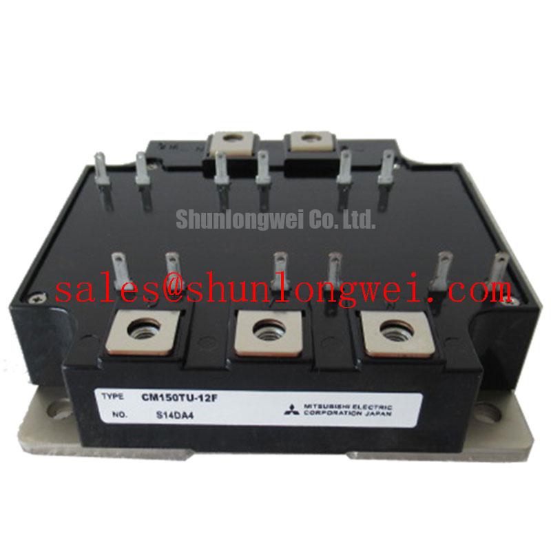
CM150TU-12F by Mitsubishi: A Robust 600V Dual IGBT for Industrial Power Systems
The Mitsubishi CM150TU-12F, a key component in the F-Series of IGBT Modules, is engineered as a high-reliability dual (2-in-1) device for demanding power conversion applications. It delivers a balanced combination of conduction efficiency and robust construction, featuring core specifications of 600V, 150A, and a maximum collector-emitter saturation voltage (Vce(sat)) of 2.7V. This translates to key engineering benefits of reduced thermal load and simplified mechanical integration. For systems engineers designing high-reliability 200-240V AC line systems, this module provides a proven and effective switching solution. What is the primary benefit of its low Vce(sat)? Lower energy waste as heat, leading to more efficient and reliable operation.
Key Parameter Overview
Decoding the Specs for Efficient Power Conversion
The electrical characteristics of the CM150TU-12F are tailored for performance and reliability in high-power switching applications. The specifications outlined below are critical for system design, particularly for thermal modeling and gate drive optimization. The low collector-emitter saturation voltage is a defining feature, directly impacting conduction losses and overall system efficiency.
| Parameter | Symbol | Value | Conditions |
|---|---|---|---|
| Collector-Emitter Voltage | VCES | 600V | VGE = 0V |
| Collector Current (DC) | IC | 150A | TC = 25°C |
| Collector-Emitter Saturation Voltage | VCE(sat) | 2.2V (typ), 2.7V (max) | IC = 150A, VGE = 15V |
| Total Power Dissipation | PC | 520W | TC = 25°C per IGBT |
| Thermal Resistance (Junction to Case) | Rth(j-c) | 0.20°C/W | IGBT Part |
| Operating Junction Temperature | Tj | -40 to +150°C |
Download the CM150TU-12F datasheet for detailed specifications and performance curves.
Application Scenarios & Value
System-Level Benefits in Motor Drives and Power Supplies
The CM150TU-12F is optimally suited for applications where reliability and efficiency are paramount. Its robust design makes it a workhorse for industrial systems operating on 200-240V AC lines.
For engineers developing a Variable Frequency Drive (VFD) for a mid-sized induction motor, the CM150TU-12F offers a compelling solution. In such a scenario, the challenge is often managing heat within a sealed enclosure while ensuring the drive can handle continuous operational loads. The module's low VCE(sat) of 2.2V (typical) at its nominal 150A current directly translates to lower conduction losses. Think of VCE(sat) as the "energy toll" the current pays to pass through the switch; a lower toll means less energy is wasted as heat. This reduction in waste heat simplifies the Thermal Management strategy, potentially allowing for a smaller heatsink or reduced fan requirements, which in turn saves space and improves the system's acoustic profile.
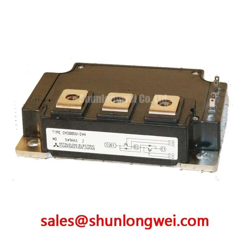
The module's dual configuration integrates two IGBTs in a half-bridge topology, which is the fundamental building block for a three-phase inverter. This integration reduces component count and simplifies the power stage layout compared to using discrete components. While the CM150TU-12F is ideal for 600V systems, for applications requiring operation on higher voltage buses, the CM150DY-24H provides a 1200V rating in a similar current class.
Technical Deep Dive
Analyzing Conduction Loss and Thermal Design Implications
A critical aspect of power module selection is a thorough analysis of losses, as this directly dictates thermal design and system reliability. For the CM150TU-12F, the collector-emitter saturation voltage, VCE(sat), is a pivotal parameter for calculating conduction losses. The datasheet specifies a typical VCE(sat) of 2.2V at the rated collector current of 150A. This allows an engineer to make a first-order calculation of conduction power loss (Pcond) per switch during the on-state: Pcond = VCE(sat) × IC. At full load, this amounts to 2.2V × 150A = 330 Watts.
This 330W of heat must be effectively transferred from the IGBT junction to the ambient environment. This is where the thermal resistance, Rth(j-c), of 0.20°C/W becomes crucial. This value represents the thermal barrier between the silicon chip and the module's case. A lower Rth(j-c) signifies more efficient heat extraction from the active silicon. Understanding the relationship between VCE(sat) and thermal resistance is fundamental to preventing the junction temperature from exceeding its 150°C maximum limit and ensuring long-term operational stability.
Frequently Asked Questions
Engineering Questions on Integration and Performance
How does the CM150TU-12F's VCE(sat) of 2.7V (max) impact thermal design?
The maximum VCE(sat) of 2.7V is the worst-case scenario for calculating conduction losses (P = Vce * Ic). Using this value ensures your thermal design, including heatsink and airflow, can maintain the junction temperature below the 150°C maximum even under maximum load and component tolerance variations, guaranteeing system reliability.
What is the significance of the 'TU' in the part number CM150TU-12F?
In the Mitsubishi Electric naming convention, 'TU' typically indicates a two-unit or dual IGBT module. This means the package contains two IGBT switches, commonly configured as a half-bridge, making it ideal for one leg of a three-phase inverter. Understanding this helps in quickly identifying the module's internal topology from its part number.
Can CM150TU-12F modules be paralleled for higher current applications?
While paralleling IGBT modules is a common technique, it requires careful engineering. To ensure proper current sharing, factors like gate drive symmetry, bus bar layout, and thermal matching must be addressed. It is critical to consult application notes from the manufacturer, like those on Mitsubishi CSTBT™ technology, for guidance on layout and component selection to prevent current imbalance and potential module failure.
Strategically, the CM150TU-12F serves as a foundational component for industrial power electronics. Its adoption in a design represents a decision for proven technology and predictable performance. For organizations focused on creating cost-effective and durable systems like general-purpose inverters and servo controls, this module provides a low-risk, high-value building block that balances performance against the total cost of ownership by simplifying thermal design and leveraging a widely available package footprint.