
Content last revised on April 14, 2026
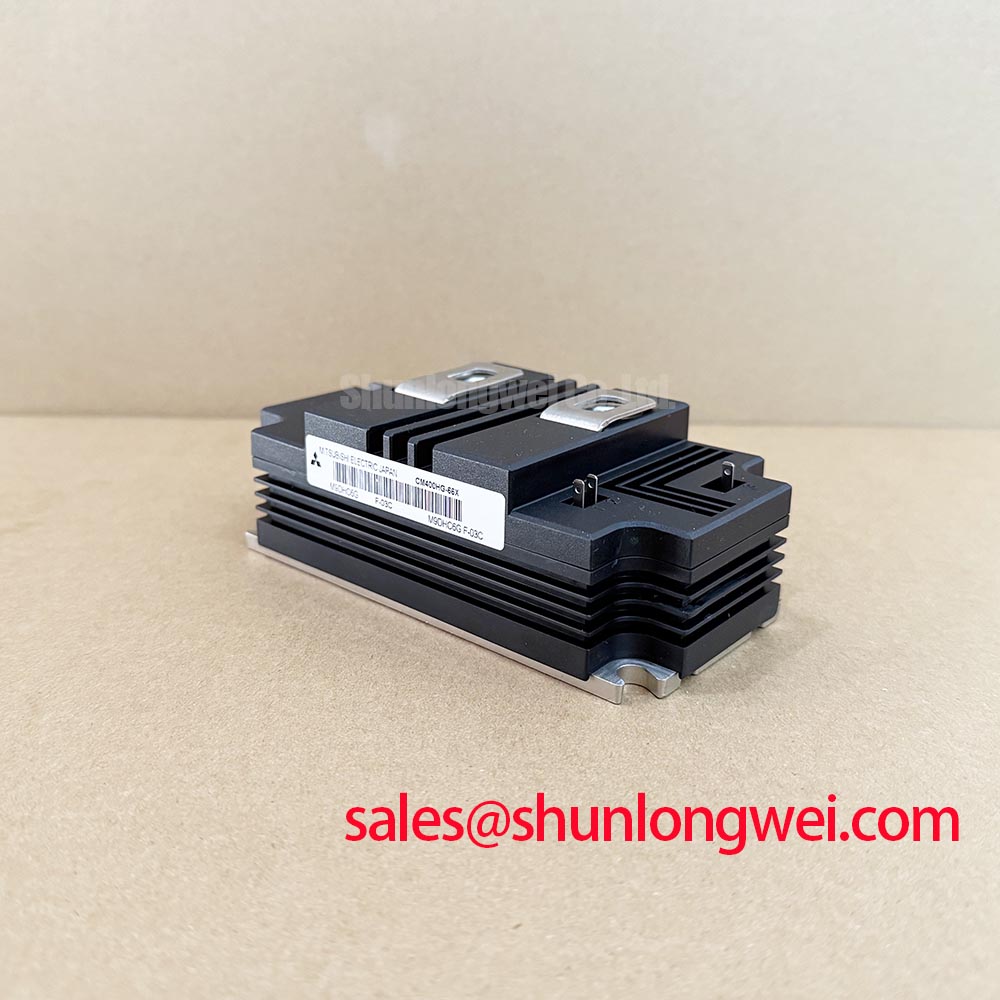
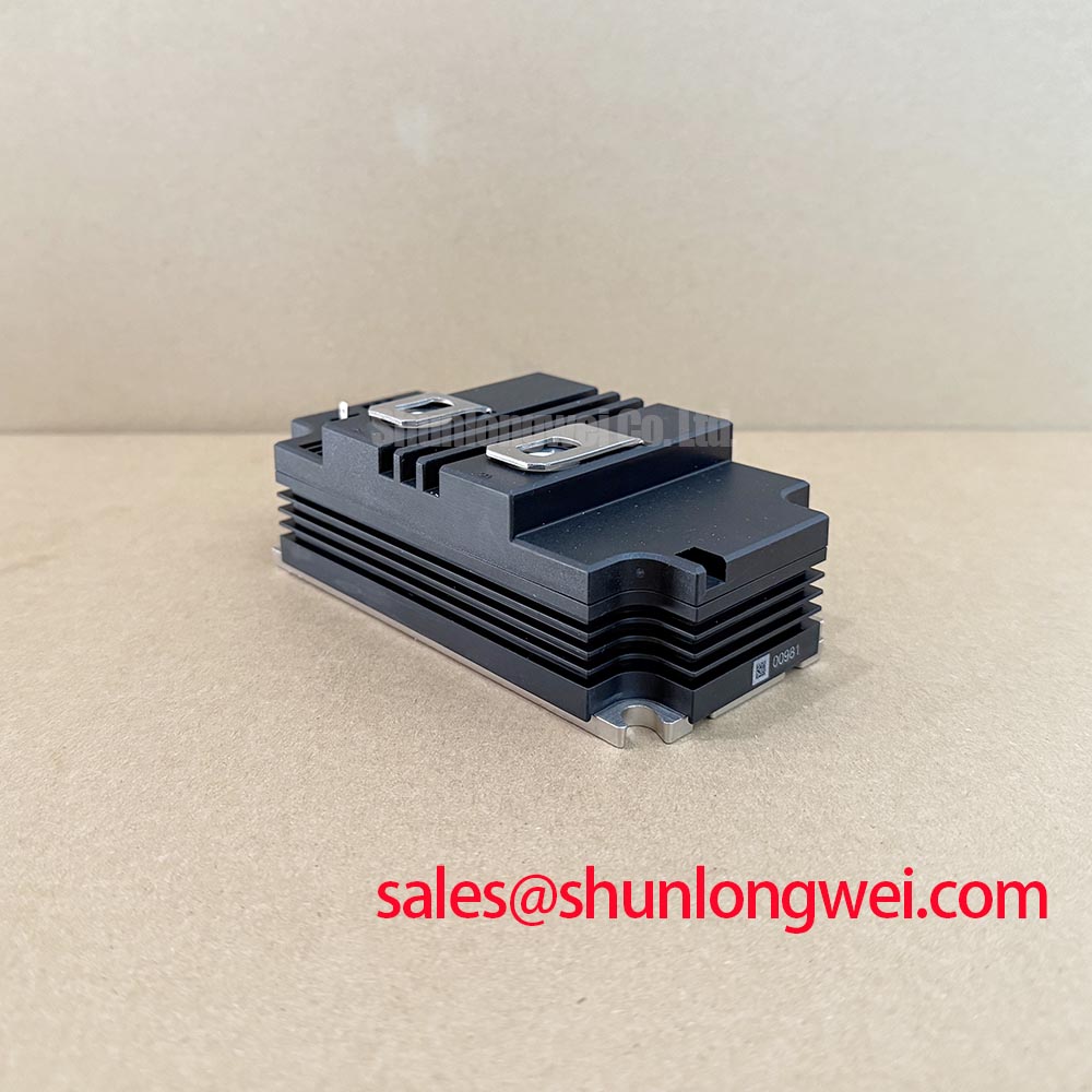
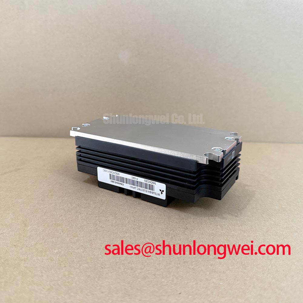
CM400HG-66X: 3300V 400A HVIGBT Module
How do you maintain switching efficiency and thermal stability in multi-megawatt traction drives without compromising electrical isolation? Engineered for heavy-duty locomotives and grid-level inverters, the CM400HG-66X leverages an AlSiC baseplate and advanced carrier-stored trench-gate technology to deliver exceptional thermal cycling capability and high-isolation reliability. What is the primary benefit of the AlSiC baseplate? It matches the silicon's thermal expansion, significantly extending power cycling reliability. Key benefits include drastically reduced conduction losses and superior dielectric strength of 10.2kVrms. For 3.3kV traction drives prioritizing long-term thermal margin and robust isolation, this AlSiC-based module is the optimal choice.
Immediate Answers to Core Engineering Queries
Clearing Up the Specs for High-Voltage Integrators
- How does the 10.2kVrms isolation voltage benefit heavy-duty applications?
It ensures robust safety margins against high-voltage transients commonly experienced in railway networks, protecting control logic from catenary voltage spikes. - What role does the AlSiC baseplate play in thermal management?
It minimizes the coefficient of thermal expansion (CTE) mismatch with the internal ceramic substrate, drastically reducing solder fatigue during aggressive load fluctuations. - Is the CM400HG-66X a single or dual switch configuration?
This is a 1-in-1 (single-element) module, granting engineers maximum flexibility when designing custom phase-leg layouts for high-power converters. - Why is the carrier-stored trench-gate architecture crucial for this 3300V module?
This specific architecture lowers the on-state voltage drop compared to planar designs, curbing steady-state conduction losses in high-current states. - Can this module be paralleled for higher current requirements?
Yes, its positive temperature coefficient allows for highly stable current sharing, preventing thermal runaway when scaling up multi-megawatt topologies.
Key Parameter Overview
Decoding the Specs for Enhanced Thermal Reliability
| Key Specification | Engineering Value Interpretation |
|---|---|
| 3300V Collector-Emitter Voltage (VCES) | Provides massive blocking capability, enabling operation in 1500V to 2000V DC-link environments without sacrificing cosmic ray breakdown margins. |
| 400A Continuous Collector Current (IC) | Delivers substantial continuous current-carrying capability, essential for driving large propulsion motors. |
| 10.2kVrms Isolation Voltage (Viso) | Guarantees industry-leading dielectric strength to meet stringent international transportation and grid safety standards. |
| AlSiC (Aluminum Silicon Carbide) Baseplate | Enhances lifecycle durability by structurally mitigating thermal-mechanical stress at the heatsink interface. |
| Integrated RFC Diode | Reduces reverse recovery charge and losses, directly boosting overall switching efficiency during free-wheeling periods. |
Download the CM400HG-66X datasheet for detailed specifications and performance curves.
Technical Deep Dive
Mitigating Thermal-Mechanical Stress with AlSiC and Advanced Silicon
When engineering high-voltage power stages, managing the microscopic physical expansion of materials is just as critical as managing electrons. The CM400HG-66X combats fundamental physics by combining two strategic technologies: an Aluminum Silicon Carbide (AlSiC) baseplate and Mitsubishi CSTBT™ (Carrier Stored Trench-Gate Bipolar Transistor) silicon.
Consider the AlSiC baseplate as an engineered thermal shock absorber. In traditional copper-based modules, the severe temperature fluctuations of traction loads cause the copper to expand at a vastly different rate than the brittle ceramic substrate above it. Over time, this CTE mismatch induces micro-cracks in the solder layers. AlSiC exhibits a CTE closely matched to the ceramic, practically eliminating this stress and multiplying the module's power cycling lifespan. For further insights into thermal dynamics, review our guide on Thermal Management.
Simultaneously, think of the CSTBT™ structure as a highly efficient traffic management system for charge carriers. By introducing a carrier-stored layer beneath the trench gate, it artificially increases the carrier density on the emitter side. This manipulation achieves a lower on-state voltage drop (VCE(sat)) traditionally impossible for a 3300V device, yielding cooler operation and less demand on the AlSiC heat dissipation pathway.
Application Scenarios & Value
Achieving System-Level Benefits in Traction and Grid Topologies
Engineers often face the challenge of managing immense thermal surges and electrical stress during the acceleration phase of heavy electric locomotives. The integration of the CM400HG-66X into these systems provides a definitive operational advantage.
In modern railway traction networks, the overhead catenary voltage frequently fluctuates, requiring power stages with extreme overhead margins. By acting as the high-side or low-side switch of a heavy-duty DC chopper or an HVDC converter, this 400A device easily absorbs these grid anomalies while maintaining highly efficient propulsion control. The single-switch format allows propulsion designers to physically distribute the thermal load across vast heatsinks, avoiding localized hot spots.
While this 400A module effortlessly handles standard regional transit, engineers scaling up to high-speed rail systems demanding extreme current density might find the FZ1500R33HE3—which provides a 1500A rating—more appropriate. Alternatively, for designers seeking a dual configuration at the exact same voltage level, the FF400R33KF2C offers an alternate physical footprint. Understanding how these industrial applications scale is the key to designing robust, fail-safe transit infrastructure.