

Content last revised on October 13, 2026
Field Diagnostics and Commissioning: Heatsink Contact Pressure in CM15LD-12H Topologies
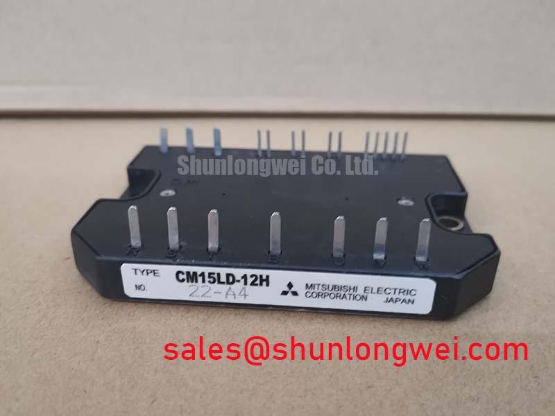
When a servo actuator shows rising case temperature, inspect the heatsink interface before changing switching parameters. The CM15LD-12H is specified as a Mitsubishi Electric IGBT module with a 600.0 V voltage rating and a 15.0 A current rating in a module package. These ratings are subject to the manufacturer’s specified conditions; the permissible operating point in a complete drive remains dependent on switching frequency, duty cycle, cooling conditions, and the application circuit.
A flat, clean heatsink surface is essential because uneven contact can leave air pockets beneath the module base. As a Design Consideration, apply a controlled and uniform thermal interface layer rather than relying on pressure to spread an excessive amount of compound. A practical maintenance procedure is to remove the module, clean both mating surfaces with a suitable process, inspect for scratches or raised areas, and check that the baseplate sits naturally before tightening.
Where the mechanical design permits, the thermal interface material should be controlled within the equipment maker’s specified thickness range. Voids, excessive compound, or a curved heatsink can increase thermal resistance and produce uneven temperature distribution across the module.
Use a sequential tightening pattern so the module settles progressively against the heatsink instead of being levered down from one corner. The final tightening method, screw grade, washer arrangement, and torque must follow the applicable mechanical drawing. Keep the power path short and maintain physical clearance around the module so that cables do not apply side loads to the terminals. After commissioning, compare temperature rise across repeated motion cycles and inspect the fan path for dust accumulation or restricted airflow.
Maintenance Note: Check heatsink cleanliness, airflow, interface-material condition, and terminal temperature during scheduled service rather than waiting for an overtemperature trip.
For a replacement assessment, compare the original circuit topology, terminal arrangement, mounting pattern, and electrical ratings before installation. The CM200DXD1-24A may be reviewed as a separate Mitsubishi Electric module reference, but any substitution requires a complete mechanical and electrical compatibility review.
Field Diagnostics and Commissioning: Transmission Line Impedance in CM15LD-12H Topologies
Long motor leads can transform an otherwise acceptable switching waveform into a terminal-voltage stress problem. In a precision stepper or BLDC servo actuator, cable length, motor impedance, grounding arrangement, switching edge rate, and filter placement interact with the inverter output. A measured spike approaching twice the DC link voltage is a serious design indication that requires immediate oscilloscope verification at the module terminals and at the motor end of the cable.
Do not size an output filter or choke from motor voltage alone. Designers should evaluate the complete cable network, switching waveform, common-mode path, motor insulation requirements, and the drive manufacturer’s filter recommendations. The engineering objective is to limit overshoot and ringing while preserving the required current response for position control. Any filter selection should be validated under the actual acceleration, deceleration, regeneration, and cable-routing conditions.
The gate-drive loop deserves the same attention. Minimize the power commutation loop and gate-return path to reduce parasitic inductance, then examine the gate waveform for ringing around the Miller plateau. A gate resistor, ferrite element, or active damping arrangement may be evaluated as a Typical Starting Point, but the final value is system-determined and must be tuned against switching loss, noise, turn-off behavior, and protection response.
Desaturation protection should be coordinated with the actual driver, sensor path, and short-circuit behavior of the inverter. The response time must be selected against the device’s documented fault limits and validated in the application, rather than treated as an inherent CM15LD-12H protection feature. A two-stage soft turn-off approach can reduce the voltage excursion associated with abruptly interrupting fault current, but the gate driver must be checked for its blanking interval, fault latch behavior, isolation performance, and reset sequence.
For gate-drive review, maintenance and commissioning teams can consult Mitsubishi Electric’s Global Semiconductor Device Technologies information and the Power Semiconductors and High-Power Modules technical resource. These references provide manufacturer-level context for power semiconductor integration without replacing the specific drive schematic and switching test data.
CM15LD-12H Operational Boundaries: Torque Reaction and Terminal Mechanics
Power connections must carry electrical current without transferring motor-cable vibration into the module’s internal conductor joints. Where the surrounding assembly uses screw-fastened cable lugs, begin by checking that the cable lug is aligned with the terminal face and that the washer bears evenly on the lug. Excessive thread engagement, a tilted lug, or a cable routed under tension can create a levering force when the equipment vibrates or cycles between hot and cold conditions. These checks apply to the assembly’s screw connections, not necessarily to the module’s own terminals.
The mounting arrangement should allow the cable to approach the connection without sharp bending immediately beside the module. Support heavy conductors independently so the electrical connection is not used as a structural anchor. During inspection, look for discoloration, damaged connections, or changes in the cable position, as well as washer movement, loosened hardware, or damaged threads wherever fasteners are used. These observations are useful maintenance evidence, but none alone establishes the internal condition of the semiconductor.
Torque control is a Design Consideration governed by the terminal size, fastener material, washer type, and applicable mechanical documentation wherever screw-fastened connections are used. Use a calibrated tool and record the service result. Do not infer a permissible terminal torque from the 600.0 V or 15.0 A electrical rating. After securing the connections, confirm that the cable remains free from mechanical tension and that the enclosure does not transmit fan or motor vibration directly into the power assembly.
In a servo motion actuator, inspect the complete path from the DC link to the module, from the module to the motor cable, and from the heatsink to the cabinet airflow. Engineers often evaluate modules of this class for precision stepper and BLDC motor servo systems, subject to the original drive topology, cooling method, protection circuit, and mechanical interface. Commissioning should record terminal temperature, switching behavior, fault response, and thermal stability under the intended motion profile.