


Content last revised on April 14, 2026
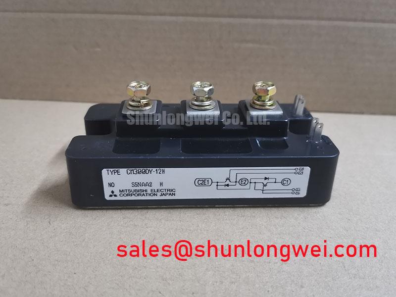
Mitsubishi CM300DY-12H: An Engineer's Guide to this 600V/300A Dual IGBT Module
The Mitsubishi CM300DY-12H is a dual IGBT module engineered for high-power switching, balancing robust current handling with thermal efficiency for demanding industrial applications. It integrates two IGBTs in a half-bridge configuration, delivering a foundation for efficient inverter and motor control designs. With core specifications of 600V | 300A | VCE(sat) 2.8V, this module provides low conduction losses and simplified thermal management. It directly addresses the need for reliable power stages in systems like AC motor drives and uninterruptible power supplies. For applications requiring a higher blocking voltage, the related CM300DY-24H offers a 1200V capability within a similar design framework.
Key Parameter Overview
Decoding the Specs for Efficient Power Conversion
The technical specifications of the CM300DY-12H are foundational to its performance in high-frequency and high-current environments. Each parameter is critical for system design, from calculating losses to ensuring long-term reliability.
| Parameter | Symbol | Value | Conditions |
|---|---|---|---|
| Collector-Emitter Voltage | VCES | 600V | VGE = 0V |
| Gate-Emitter Voltage | VGES | ±20V | VCE = 0V |
| Collector Current (DC) | IC | 300A | TC = 25°C |
| Peak Collector Current | ICM | 600A | Pulse, Tch not exceeding Tj(max) |
| Collector-Emitter Saturation Voltage | VCE(sat) | 2.8V (Max) | IC = 300A, VGE = 15V |
| Maximum Collector Dissipation | Pc | 1100W | TC = 25°C |
| Isolation Voltage | Viso | 2500Vrms | AC 1 minute |
| Junction Temperature | Tj | -40 to +150°C | Operating |
Download the CM300DY-12H datasheet for detailed specifications and performance curves.
Application Scenarios & Value
System-Level Benefits in Motor Control and Power Conversion
The CM300DY-12H is designed for robust performance in a range of high-power switching applications. Its dual-IGBT, half-bridge configuration makes it a versatile building block for three-phase inverters and other power topologies. The module's isolated baseplate simplifies mechanical assembly and thermal design by allowing direct mounting to a common heatsink, which can reduce manufacturing complexity and cost.
A key engineering challenge in Servo Drive design is managing conduction losses to maximize efficiency and minimize heat. The CM300DY-12H's maximum VCE(sat) of 2.8V at its rated 300A current is crucial here. Think of VCE(sat) as the "toll" the current pays to pass through the switch. A lower toll means less energy is wasted as heat. This allows for smaller heatsinks or higher power density in the final design. For designers of industrial motor controls, this directly translates to more compact and energy-efficient systems.
Core applications for this module include:
- AC Motor Control: The half-bridge topology is ideal for constructing the inverter stages of Variable Frequency Drives (VFDs).
- Uninterruptible Power Supplies (UPS): Its current handling and fast-switching capabilities are well-suited for the inverter and converter stages in high-capacity UPS systems.
- Welding Power Supplies: The module can reliably handle the high-current pulses required in advanced welding equipment.
- Motion/Servo Control: Provides the precise and rapid power switching needed to control industrial servo motors with high accuracy.
Frequently Asked Questions (FAQ)
What is the primary benefit of the half-bridge configuration in the CM300DY-12H?
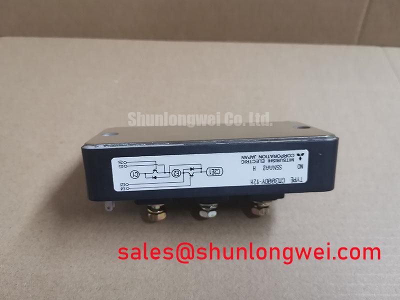
The integrated half-bridge (two IGBTs in series) is a fundamental building block for creating inverters. Using a single module simplifies the power stage layout, reduces stray inductance compared to using discrete components, and streamlines the assembly process for applications like three-phase motor drives.
How does the VCE(sat) of 2.8V impact thermal design?
A lower Collector-Emitter Saturation Voltage (VCE(sat)) means lower conduction losses (Power Loss = VCE(sat) x IC). With a VCE(sat) of 2.8V at 300A, the module generates less heat during operation. This reduces the demands on the cooling system, potentially allowing for a smaller, lighter, or lower-cost heatsink to maintain the junction temperature within its safe operating limits of -40 to 150°C.
What does the 2500Vrms isolation voltage signify for system safety?
The 2500Vrms isolation rating between the active terminals and the baseplate is a critical safety feature. It ensures that high voltages on the power circuit are safely isolated from the grounded chassis and heatsink. This simplifies meeting safety standards like those from UL (the module is UL Recognized) and protects both equipment and personnel from potential electrical shock hazards.
For inquiries or to discuss your specific design requirements, please contact our technical support team.