
Content last revised on October 8, 2026
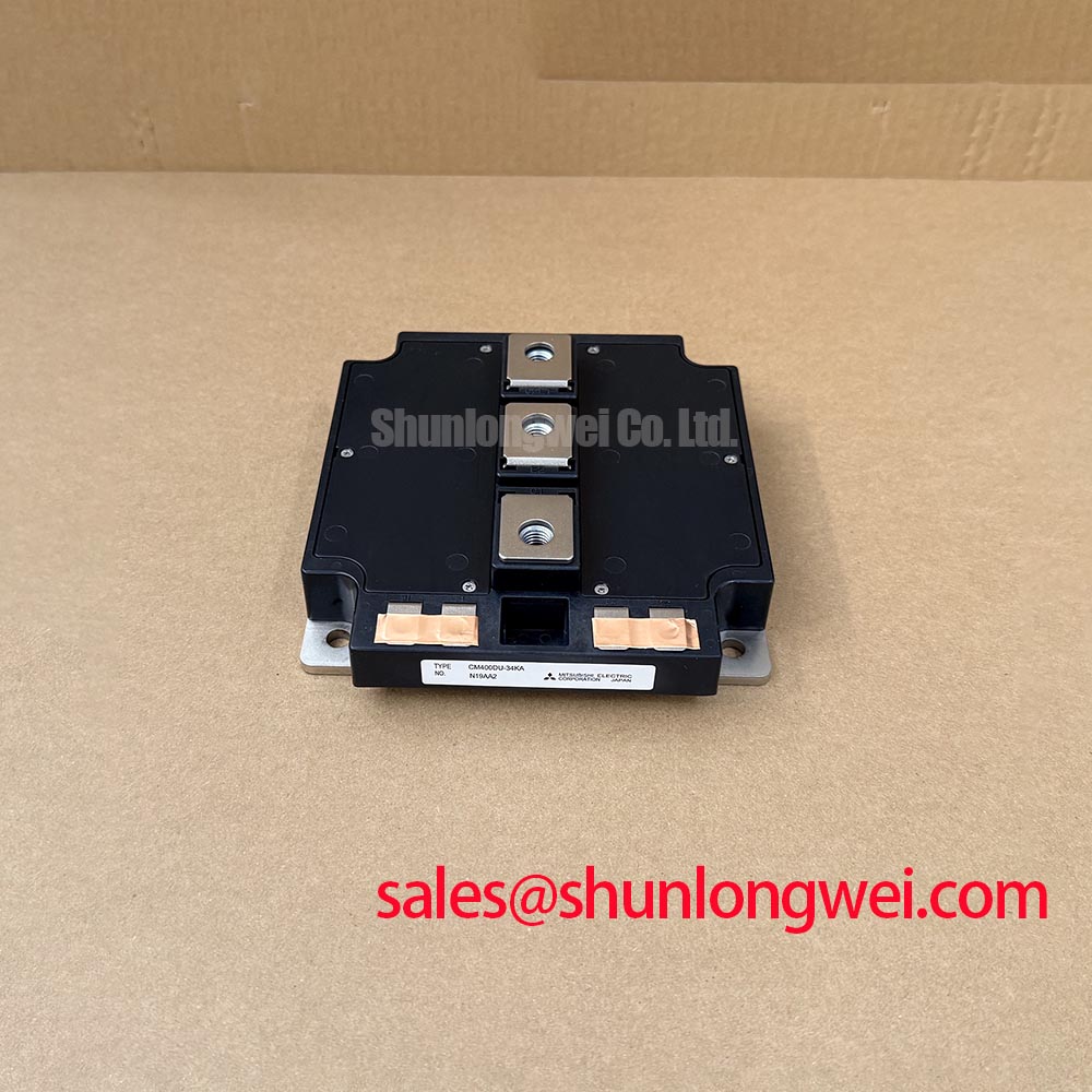
CM400DU-34KA Inspection and Identification
Isolate the converter, verify that its DC link is discharged, and disconnect the gate connections before checking the CM400DU-34KA for terminal damage or abnormal resistance between power terminals. On a wind turbine converter service bench, measurements taken through connected busbars, snubbers, or driver boards can obscure the condition of the module itself. Record the terminal markings and wiring positions before removal, then compare isolated measurements with the equipment documentation and a known-good assembly where available.
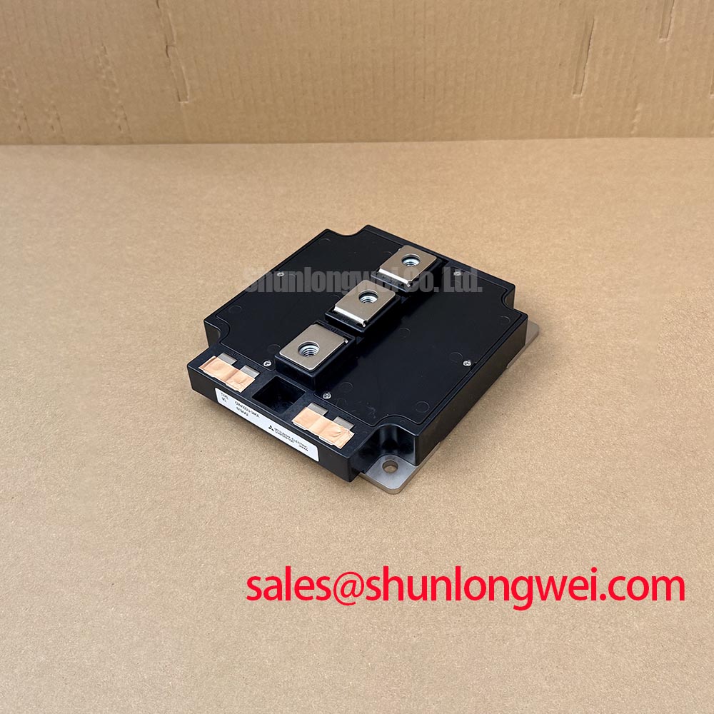
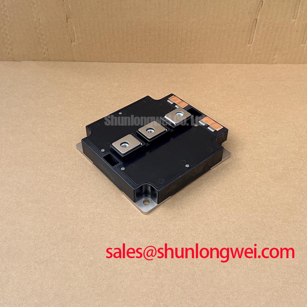
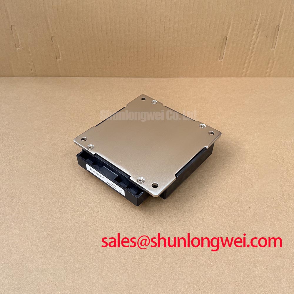
The Mitsubishi Electric CM400DU-34KA is an IGBT module with an official voltage rating of 1700 V and current rating of 400 A. These ratings establish component identification boundaries; they do not independently establish permissible converter output, switching frequency, cooling requirements, or short-circuit protection timing. For evaluation in a multi-megawatt offshore or onshore wind turbine full-scale converter, the installed power-stage schematic and the original module documentation remain essential compatibility references.
| Identification item | Value | Specification status |
|---|---|---|
| Model | CM400DU-34KA | Manufacturer model designation |
| Manufacturer | Mitsubishi Electric | Product identification |
| Voltage rating | 1700 V | Official Specification |
| Current rating | 400 A | Official Specification; applicable operating conditions must be checked in the original datasheet |
| Package | Module | Official Specification |
Mitigating Hard Switching Transients via Active Desaturation Soft Shutdown
Start a repeated trip investigation at the driver interface, not by assuming the replacement module is defective. As a Design Consideration, examine the gate supply, gate return, desaturation sensing path, fault latch, and controller response together. Capture the sequence of gate command, collector-emitter voltage, and driver fault indication using suitably rated, isolated measurement equipment. A fault occurring during a switching transition needs different investigation from one detected after the device has already entered normal conduction.
Type-I and type-II short-circuit events describe different operating circumstances: switching into an existing short circuit and encountering a fault while already conducting. Those distinctions matter to the protection circuit, but neither the acceptable detection delay nor the allowable fault duration can be inferred from the 1700 V, 400 A ratings. The protection deadline must come from the CM400DU-34KA short-circuit safe operating area, its stated test conditions, and the driver’s complete response time. A generic microsecond limit is not a verified specification for this module.
As a Design Consideration, desaturation blanking should reject normal turn-on behavior without masking a genuine fault. Engineers should examine sensing-diode connections, contamination around high-voltage sensing nodes, and the integrity of the emitter reference. A damaged connector or an unsuitable reference path can disturb the sensed voltage. Check these possibilities against measured waveforms rather than assigning a single cause to a desaturation alarm.
A two-stage soft shutdown can be evaluated as a system protection method: first reduce fault current through controlled gate discharge, then complete turn-off. Its usefulness depends on fault current, gate-driver behavior, parasitic inductance, and the device’s permitted operating envelope. Excessively abrupt interruption can increase inductive overshoot, while excessively slow shutdown can prolong device heating. The shutdown profile therefore requires validation on the actual power stage; it is not a fixed setting supplied by the module’s headline ratings.
Inspect separation between gate wiring and high-current conductors, then verify creepage and clearance against the converter’s applicable insulation requirements. Cable routing, connectors, pollution conditions, and enclosure construction all affect that assessment. The Field Engineer’s Handbook provides related testing and failure-analysis context, while product-specific protection limits must remain tied to the original manufacturer documentation.
Thermal Feedback & V_CE(sat) Positive Temperature Coefficient Equalization
When a converter has uneven temperature readings or unequal branch currents, first establish whether it actually operates modules in parallel. Do not infer the installed topology from the model name or from adjacent mounting positions. Trace the power connections against the schematic and verify every gate and emitter connection against the manufacturer’s terminal drawing. Correct terminal identification is especially important when a service replacement arrives with a different arrangement of labels, harnesses, or busbar adapters.
As a Design Consideration, a positive temperature coefficient of collector-emitter saturation voltage can support static current sharing in an appropriate operating region. That behavior must be confirmed from the CM400DU-34KA characteristic curves before being used in a parallel-operation assessment. It does not guarantee equal current across every load and temperature condition. Contact resistance, cooling differences, device characteristics, and conductor geometry can still produce an uneven distribution.
Static sharing and dynamic sharing need separate checks. During conduction, compare branch-current measurements with case-temperature trends and voltage drops across accessible connections. During switching, examine gate timing and the relationship between gate-emitter voltage and branch current. Symmetrical gate-loop wiring is an engineering consideration for reducing differences in switching response, but apparently identical wire lengths alone do not establish equivalent impedance or equal switching losses.
Wind turbine converter service also calls for inspection of mechanically loaded connections. Look for displaced fasteners, damaged supports, stressed cable lugs, and busbar contact surfaces affected by heating. Any vibration-resistant fastening arrangement should follow the equipment’s mechanical specification rather than an improvised locking method. Maintain the specified electrical spacing after reassembly; a displaced conductor or added washer can change both clearance and mechanical loading.
For procurement comparison, the CM400HA-12E is another Mitsubishi module designation that may appear in maintenance records or supplier searches, but it must not be treated as a confirmed substitute for the CM400DU-34KA. Compare voltage rating, circuit arrangement, terminal mapping, package drawing, gate characteristics, and thermal data before considering any substitution. Shared branding or a similar model prefix is insufficient evidence of compatibility.
Planar Symmetrical Busbar Geometry: Controlling Stray Inductance and Turn-Off Overshoot
Inspect the DC-link-to-module connection before changing the gate circuit to address turn-off overshoot. As a Design Consideration, closely coupled outgoing and return current paths can reduce commutation-loop inductance. Check whether a replacement busbar preserves the original overlap, spacing, support arrangement, and connection surfaces. An adapter that makes a module physically fit can also alter the switching loop, so dimensional compatibility and electrical compatibility need separate approval.
The relevant Engineering Calculation is that peak switch voltage is approximately the DC-link voltage plus stray inductance multiplied by the rate of current change. This explains why reducing loop inductance or moderating turn-off can reduce overshoot, but it does not establish a universal inductance target for this module. The permissible peak must be assessed against the manufacturer’s operating limits, actual DC-link conditions, and measured switching behavior.
Measure collector-emitter voltage with a probe arrangement suited to the voltage and transient environment. Probe-loop pickup, common-mode response, and bandwidth limitations can distort the observed peak. Repeat the measurement with a controlled connection geometry before concluding that a waveform represents the voltage across the semiconductor. Compare equivalent switching positions under comparable conditions rather than relying on a single trace captured during an uncontrolled trip.
Snubber selection is also system-determined. Designers should evaluate the ringing frequency, commutation energy, capacitor pulse capability, resistor dissipation where applicable, and physical placement. A snubber located away from the relevant current loop may not control the local transient as intended. No capacitance value or stray-inductance threshold follows directly from the CM400DU-34KA voltage and current ratings.
Keep auxiliary power-conversion circuits distinct from the main converter switching stage during diagnosis. The operating principles described in Buck Converter Step-Down Voltage Regulation can help interpret a documented step-down supply, while Forward Converter Single-Ended Transformer Topology explains a different transformer-based arrangement. These are topology references, not evidence that either circuit is present in the particular wind turbine converter or inside this module.
Baseplate Convexity Compensation and Screw Tightening Sequence Guidelines
Before fitting the replacement, clean and inspect the heatsink contact surface and the module mounting surface. Remove residual interface material without damaging the mating surfaces, and check for raised debris, scratches, corrosion, or distortion that could prevent consistent contact. If an apparent baseplate curvature is found, compare it with the manufacturer’s mechanical requirements rather than attempting to flatten the module by increasing bolt force.
As a Design Consideration, thermal interface material should fill surface irregularities without creating an unnecessarily thick thermal barrier. Its application depends on material properties, surface condition, mounting pressure, and the approved assembly method. The CM400DU-34KA installation should use the manufacturer’s documented interface procedure; a generic paste thickness cannot be presented as an official requirement. Where a pad is specified, confirm its suitability instead of replacing it with grease solely for convenience.
⚠️ Field Alert: Use the documented mounting torque and tightening sequence, and never use the busbar fasteners to pull a misaligned module into position.
Seat the module without forcing the power terminals into alignment. Where the approved procedure specifies progressive tightening, bring the mounting screws into engagement and tighten them in the documented sequence. Mounting screws and terminal screws serve different mechanical functions and may have different requirements. Confirm the specified hardware, washer arrangement, thread engagement, and torque for each connection rather than applying one setting throughout the assembly.
Complete the mechanical inspection before restoring gate power. Verify terminal spacing, cable support, connector seating, and the absence of tools or loose hardware around the power stage. During the equipment’s approved commissioning procedure, compare temperature trends and fault behavior across equivalent positions. An unexpected hot spot should prompt checks of cooling contact, terminal resistance, current distribution, and sensing accuracy; temperature alone does not identify a single failure mechanism.
For the replacement record, retain the CM400DU-34KA designation, its 1700 V and 400 A ratings, the terminal-map verification, and the mounting procedure used. Record measured switching waveforms and thermal observations under their actual test conditions so the next service decision rests on traceable evidence rather than an assumed drop-in fit.