Content last revised on August 28, 2026
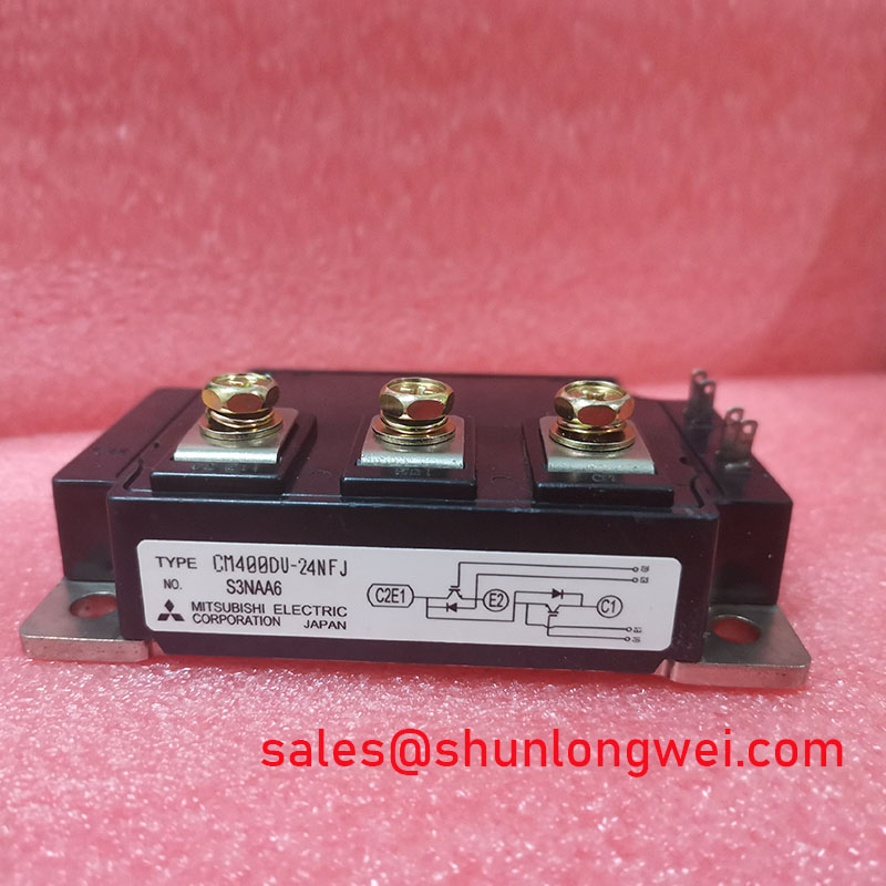
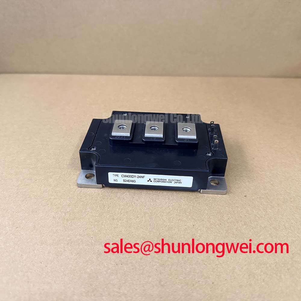
CM400DU-24H Mitsubishi 1200V 400A Dual IGBT Module
How do design engineers maintain high-efficiency thermal dissipation and stable switching margins in heavy-duty 400A inverter designs? The Mitsubishi CM400DU-24H dual IGBT module provides robust, low-loss power switching for demanding industrial motor drives. Rated at 1200V and 400A with a junction-to-case thermal resistance of 0.06°C/W, this module optimizes system reliability. Low collector-emitter saturation voltage reduces conduction loss, while the isolated copper baseplate simplifies package mounting. By combining carrier-store trench gate technology with a highly isolated baseplate, this module addresses collector-emitter thermal rise while maintaining a wide safe operating area.
Frequently Asked Questions
Resolving Critical Integration Challenges for Dual IGBT Modules
- How does the 0.06°C/W junction-to-case thermal resistance (Rth(j-c)) affect heatsink selection for the CM400DU-24H?
The thermal resistance rating of 0.06°C/W indicates high heat transfer efficiency from the silicon junction to the copper baseplate. This allows design engineers to utilize smaller heatsink profiles while maintaining safe operating junction temperatures. - What precautions should be taken when using the CM400DU-24H in parallel configurations?
Paralleling requires matching the collector-emitter saturation voltage (VCE(sat)) of the modules. Small deviations in VCE(sat) can cause uneven current sharing and thermal runaway, making voltage grouping essential.
Key Parameter Overview
Decoding Specifications for Safe Thermal Boundaries
| Parameter | Symbol | Specification Value |
|---|---|---|
| Collector-Emitter Voltage | VCES | 1200V |
| Gate-Emitter Voltage | VGES | ±20V |
| Collector Current (DC) | IC | 400A |
| Peak Collector Current | ICM | 800A |
| Emitter Current | IE | 400A |
| Max Power Dissipation (TC = 25°C) | Pc | 2100W |
| Junction Temperature Range | Tj | -40°C to 150°C |
| Collector-Emitter Saturation Voltage (Typ) | VCE(sat) | 2.9V (at IC=400A, VGE=15V) |
| Thermal Resistance (Junction-to-Case, IGBT) | Rth(j-c) | 0.06°C/W |
| Thermal Resistance (Junction-to-Case, FWDi) | Rth(j-c) (diode) | 0.13°C/W |
| Isolation Voltage (AC 1 min.) | Viso | 2500V |
Download the CM400DU-24H datasheet for detailed specifications and performance curves.
Technical & Design Deep Dive
Analyzing the Gate Drive and RBSOA Design Considerations
The electrical behavior of the CM400DU-24H relies heavily on robust gate drive design. With a typical gate charge of 1500 nC, the gate driver must deliver sufficient peak current. This is necessary to achieve fast switching transitions and avoid excessive dynamic losses. Implementing a negative gate bias (typically -15V) prevents accidental turn-on caused by high dv/dt noise.
Conduction losses are governed by the collector-emitter saturation voltage. Think of the collector-emitter saturation voltage (VCE(sat)) as friction in a water pipe. A higher VCE(sat) acts like a rough interior that slows the flow and generates heat, while a lower VCE(sat) of 2.9V ensures a smooth, unrestricted channel that minimizes thermal build-up. What is the primary benefit of the carrier-store trench gate structure? It reduces conduction losses while maintaining a stable saturation voltage.
Similarly, the thermal path dictates system longevity. The thermal resistance Rth(j-c) of 0.06°C/W behaves like a multi-lane highway for heat. Just as more lanes prevent traffic congestion, this low thermal resistance ensures heat generated at the junction is evacuated instantly to the heatsink, keeping the silicon from overheating under heavy cyclic loads. What is the primary benefit of the isolated baseplate? It simplifies thermal design by eliminating external isolation requirements.
To prevent localized thermal stress, engineers must also manage transient thermal impedance. When designing switching trajectories, keeping the peak voltage within the Reverse Bias Safe Operating Area (RBSOA) is critical for high-voltage switching. For comprehensive layout guidelines, consult our 5 practical tips for robust IGBT gate drive design. Additionally, managing these parameters helps in preventing overvoltage failures; read more in our guide on IGBT failure analysis.
Application Scenarios & Value
Optimizing Performance in Industrial Motor Drives and Inverters
For 460V industrial motor drives requiring low conduction loss, this 1200V 400A module is the optimal choice.
The module is widely used in high-power applications such as Variable Frequency Drives (VFDs), uninterruptible power supplies (UPS), and solar inverters. In heavy-duty crane VFD systems, engineers frequently battle severe starting torque requirements that draw massive inrush currents. The CM400DU-24H resolves this challenge through its 800A peak collector current rating (ICM). This rating provides the critical safety overhead required during motor startup without risking thermal breakdown. These systems often operate in environments regulated by standards such as IEC 61800-3 for EMC compliance.
For systems requiring lower current capacity, the related CM300DU-24H offers a 300A rating in a similar footprint. Conversely, if a single-IGBT configuration is preferred for custom phase designs, the CM400HA-24H provides a single-channel option. These choices allow engineers to scale their designs based on specific thermal and current requirements.
As a specialized distributor of industrial power semiconductors, we provide technical documentation and parts sourcing to support your design evaluations. For current availability, pricing, or technical inquiries regarding the CM400DU-24H, contact our sales team today.