


Content last revised on June 18, 2026
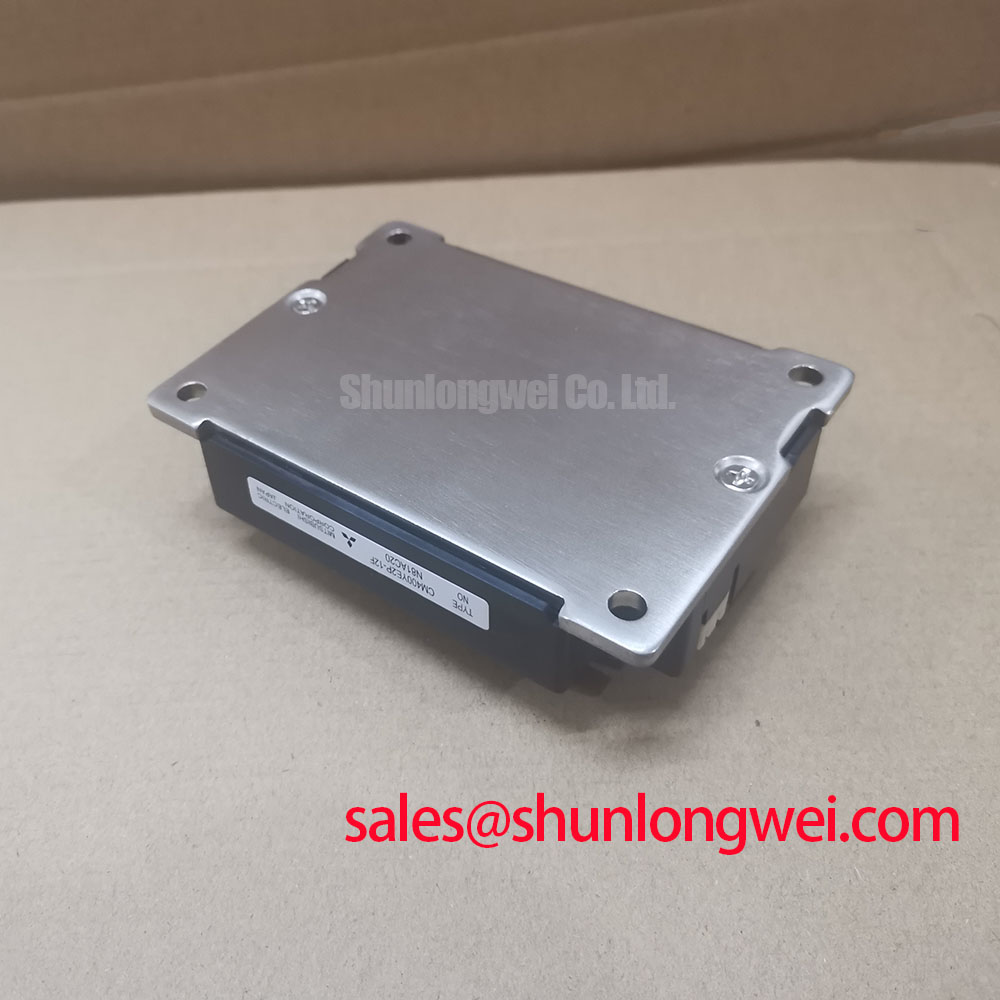
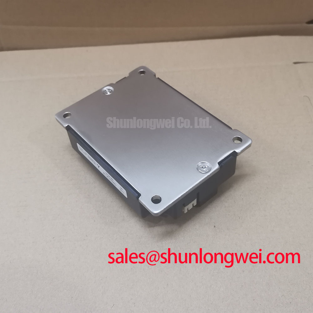
CM400YE2P-12F | 600V 400A Dual IGBT Module for High-Efficiency Power Conversion
Engineering Analysis of the CM400YE2P-12F IGBT Module
Optimizing Performance in Demanding Switching Applications
The Mitsubishi CM400YE2P-12F is a high-performance dual IGBT module engineered to deliver superior efficiency in demanding power conversion systems. With its robust 600V | 400A rating and exceptionally low saturation voltage (VCE(sat)) of 1.70V, this module directly addresses the critical engineering challenge of minimizing both conduction and switching losses. This translates to reduced thermal load, enabling higher power density and improved system reliability. What is the impact of its low switching loss? It allows designers to operate at higher frequencies, reducing the size and cost of magnetic components. For industrial drives and high-power supplies where efficiency is paramount, the CM400YE2P-12F provides a decisive performance advantage.
Application Scenarios & Value
Achieving System-Level Benefits in Motor Drives and Power Supplies
The primary value of the CM400YE2P-12F is realized in applications that demand a fine balance between high power throughput and operational efficiency. Best suited for high-frequency motor control and power supply designs, its performance characteristics enable tangible system-level improvements.
Consider the design of a modern Variable Frequency Drive (VFD). A key challenge is managing the heat generated within the inverter stage, which directly impacts the VFD's size, cost, and lifespan. The CM400YE2P-12F's low total switching energy (Ets) of 28 mJ (typical) significantly cuts down on thermal dissipation during high-frequency operation. This allows engineers to specify smaller, more cost-effective heatsinks or to push more power through a chassis of a given size, a critical factor in competitive industrial automation markets. This module's efficiency helps system designers meet stringent energy standards like IEC 61800-5-1. For systems requiring greater current handling capabilities in a similar package, the CM600YE2P-12F offers an increased rating of 600A.
Key Parameter Overview
Functional Performance Metrics for System Design
The specifications of the CM400YE2P-12F are tailored for robust performance in high-power switching circuits. The parameters below are grouped by function to facilitate engineering evaluation for applications like servo drives and uninterruptible power supplies.
| Characteristic | Symbol | Condition | Value |
|---|---|---|---|
| Absolute Maximum Ratings (Tc = 25°C) | |||
| Collector-Emitter Voltage | VCES | - | 600V |
| Gate-Emitter Voltage | VGES | - | ±20V |
| Collector Current (DC) | IC | - | 400A |
| Collector Current (Pulse) | ICP | 1ms pulse | 800A |
| Maximum Power Dissipation | PC | Per IGBT | 1560W |
| Electrical Characteristics (Tj = 25°C) | |||
| Collector-Emitter Saturation Voltage | VCE(sat) | IC = 400A, VGE = 15V | 1.70V (Typ.), 2.20V (Max.) |
| Gate-Emitter Threshold Voltage | VGE(th) | IC = 40mA, VCE = 10V | 5.5V (Typ.) |
| Collector-Emitter Cutoff Current | ICES | VCE = VCES, VGE = 0V | 1mA |
| Switching & Diode Characteristics (Tj = 125°C) | |||
| Turn-on Switching Energy | Eon | IC = 400A, VCC = 300V | 21 mJ (Typ.) |
| Turn-off Switching Energy | Eoff | 23 mJ (Typ.) | |
| Diode Forward Voltage | VEC | IE = 400A, VGE = 0V | 1.50V (Typ.) |
| Thermal Characteristics | |||
| Thermal Resistance (Junction to Case) | Rth(j-c) | IGBT | 0.08 °C/W |
| Operating Junction Temperature | Tj | - | -40 to +150°C |
Download the CM400YE2P-12F datasheet for detailed specifications and performance curves.
Frequently Asked Questions (FAQ)
What makes the CM400YE2P-12F suitable for high-frequency switching applications?
The module's suitability stems from its optimized design using Mitsubishi's advanced trench gate chip technology. This results in low typical turn-on (21 mJ) and turn-off (23 mJ) switching energies. Lower switching energy directly reduces heat generation at higher frequencies, enabling more efficient and compact system designs. For a deeper understanding of this trade-off, see our guide on IGBT selection for high-frequency designs.
What are the design advantages of the plug-in terminals on the CM400YE2P-12F compared to screw terminals?
The plug-in pin terminal design offers distinct advantages in manufacturing and maintenance. It facilitates faster, solder-based assembly onto a PCB, which can streamline production processes compared to the manual torqueing required for screw terminals. This connection method also provides excellent vibration resistance, a key reliability factor in applications such as industrial machinery and commercial vehicle power systems.
Industry Insights & Strategic Advantage
Meeting Modern Energy Efficiency and Power Density Mandates
In the era of Industry 4.0 and escalating energy costs, industrial equipment manufacturers face immense pressure to deliver products that are not only powerful but also highly efficient. Regulatory bodies worldwide are implementing stricter standards for energy consumption in industrial machinery, including the motors and drives that form the backbone of automation. The CM400YE2P-12F directly supports these strategic objectives. By integrating this module, OEMs can develop servo drives and inverters that surpass baseline efficiency requirements, offering end-users lower total cost of ownership through reduced electricity consumption. This superior efficiency is not just a feature; it is a competitive differentiator that aligns with global trends toward sustainability and smarter manufacturing.
Final Engineering Considerations
For engineers developing high-power industrial inverters or uninterruptible power supplies, the CM400YE2P-12F offers a compelling combination of high current handling and exceptional switching efficiency. To fully leverage its capabilities, review the detailed performance curves in the official datasheet to optimize your gate drive and thermal management strategy.