
Content last revised on November 1, 2026
Field Diagnostics & Commissioning: Short-Circuit Energy Let-Through Matching in CM600DU-24NFH Topologies
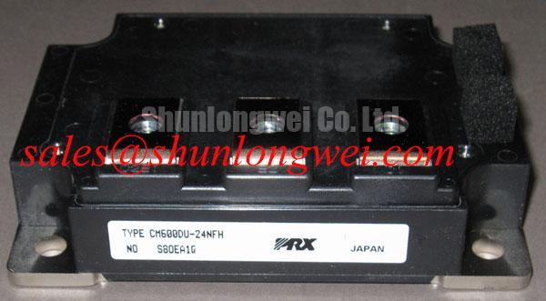
I isolate the DC link and verify discharge before tracing the fault-current path through the semiconductor fuse, busbar, and module terminals. For the Mitsubishi Electric CM600DU-24NFH IGBT module, protection coordination requires separating an external short circuit from a commanded switching event that develops excessive current. Fuse operation and gate-driver shutdown address different portions of that event; neither should be treated as a universal substitute for the other.
Design Consideration: Compare the fuse manufacturer’s total-clearing I²t at the actual circuit voltage and prospective fault current with the equipment’s documented protection coordination. Include capacitor discharge, source impedance, and interruption behavior. The module’s 1200 A pulsed collector-current rating for a 1 ms pulse is an Official Specification, not a short-circuit withstand declaration or a fuse-coordination curve. Successful interruption without enclosure damage must be established through the equipment’s protection validation, rather than inferred from that pulse rating.
The following Official Specification values define the electrical and thermal reference points for this product. Conditions belong with the numbers: they determine whether a bench reading or operating estimate is meaningfully comparable.
| Parameter | Symbol and condition | Official Specification |
|---|---|---|
| Collector-emitter voltage | VCES | 1200 V |
| Gate-emitter voltage | VGES | ±20 V |
| DC collector current | IC; case temperature 25°C | 600 A |
| Pulsed collector current | ICP; 1 ms pulse | 1200 A |
| Maximum power dissipation | PC; case temperature 25°C, per IGBT | 3470 W |
| Collector-emitter saturation voltage | VCE(sat); IC 600 A, VGE 15 V | 1.85 V typical; 2.30 V maximum |
| Gate-emitter threshold voltage | VGE(th); IC 60 mA, VCE 10 V | 5.5–7.5 V |
| Collector cutoff current | ICES; VCE 1200 V, VGE 0 V | 1 mA |
| Junction-to-case thermal resistance | Rth(j-c); IGBT | 0.036 °C/W |
| Operating junction temperature | Tj | −40 to +150°C |
Engineering Recommendation: When evaluating a regenerative braking chopper, examine the braking resistor, chopper switching command, and DC-link overvoltage response together. Resistor energy absorption and cooling are system-level requirements, not capabilities supplied by the IGBT current rating. In a repair record, preserve the fault timestamp, DC-link waveform, and driver protection indication so that resistor overload, switching malfunction, and upstream supply faults remain distinguishable.
For complementary-stage assessment, the CM300HA-24E is a separate power-device reference, not an assumed input rectifier or drop-in companion. Establish its circuit role from the schematic and its own ratings before considering any shared protection arrangement.
Preventing Spurious Faults: Terminal Engagement and Mounting Stress in CM600DU-24NFH
Check terminal screw engagement against the mounting drawing before attaching the busbar; a screw that bottoms out can appear tight without producing the intended contact pressure. Design Consideration: Account for lug thickness, washer stack, thread engagement, and terminal seating as one mechanical assembly. Support the conductor independently so that tightening does not pull the module terminal into alignment.
Mechanical leverage at an external terminal can transfer stress into the package, but intermittent resistance alone does not establish an internal crack. Compare contact behavior with the assembly stationary, inspect terminal seating, and review whether busbar expansion is being constrained. Discoloration or localized heating should prompt examination of contact pressure and surface condition rather than an automatic diagnosis of internal damage.
Engineering Recommendation: Prepare the heatsink surface, assess flatness, and apply the thermal interface material according to the approved assembly process. The objective is continuous contact without an unnecessarily thick thermal barrier. If the mounting arrangement permits progressive cross-pattern tightening, use it to distribute seating pressure, with final torque taken from the applicable module and fastener instructions rather than a generic screw-size rule.
The 3470 W maximum dissipation per IGBT at a case temperature of 25°C describes a specified thermal boundary, not an unrestricted equipment operating point. Likewise, the 0.036 °C/W junction-to-case thermal resistance excludes the interface and heatsink. Evaluate losses over the actual switching cycle, then include those additional thermal paths when checking junction temperature against the specified operating range.
During sourcing review, compare the complete electrical rating, terminal arrangement, mounting drawing, and driver requirements. The UM100CDY-10 can be retained as a separate catalog comparison, but no electrical or mechanical interchangeability with CM600DU-24NFH is established here. A shared product category is not a replacement qualification.
Field Diagnostics & Commissioning: Preventing High di/dt Gate-Loop Disturbance in CM600DU-24NFH Topologies
Trace the gate-driver return to the emitter connection identified in the module terminal drawing, rather than selecting the nearest power conductor. Design Consideration: Shared emitter-path inductance can shift the driver’s local reference during rapid current changes. Distinguish the load-current connection from any separately documented control-emitter connection; a dedicated Kelvin terminal must not be assumed from the model name or package appearance.
Measure gate-emitter voltage at the module connection using a suitably rated differential measurement arrangement with a compact probing loop. Compare the commanded off-state waveform with collector-emitter switching behavior and driver fault timing. A disturbance coincident with the opposite switch transition may involve Miller coupling, shared-return inductance, probe pickup, or driver supply movement; waveform correlation is more informative than assigning one cause from the symptom alone.
The ±20 V gate-emitter rating is an Official Specification boundary, not a suggested drive setting. The specified 5.5–7.5 V threshold is measured at only 60 mA collector current and does not define a suitable fully enhanced operating voltage. The saturation-voltage figures are instead specified at a gate-emitter voltage of 15 V and collector current of 600 A.
Design Consideration: For optocoupler or digital-isolator driver boards, compare the isolator’s specified common-mode transient immunity with measured switching-node transitions under its stated operating conditions. Examine isolated-supply movement and output behavior alongside the gate waveform. CMTI is a property of the selected isolation device and test conditions, not a module-level immunity guarantee.
Pro Tip: Keep outgoing and return busbar paths closely coupled and mechanically balanced, then verify turn-off voltage margin with a controlled double-pulse test representative of the intended operating conditions.
For manufacturer technical context, consult Mitsubishi Electric Power Semiconductors & High-Power Modules. The Wide Bandgap Revolution discussion provides comparative switching background when evaluating a technology change, not an acceptance standard or evidence of SiC or GaN interchangeability.
CM600DU-24NFH Circuit Protection & Reliability: Terminal-to-Baseplate Insulation Testing
Disconnect the module from driver electronics and external power paths before establishing a terminal-to-baseplate insulation-test connection. Engineering Recommendation: Use the manufacturer-approved test configuration, voltage, duration, terminal grouping, and discharge procedure. An insulation-resistance measurement and a dielectric-withstand test answer different questions; an arbitrary megohmmeter setting cannot substitute for the specified procedure.
Do not adopt an undocumented resistance threshold or test voltage as a CM600DU-24NFH acceptance criterion. A resistance reading depends on test conditions, surface contamination, temperature, and connected circuitry. It also cannot independently identify an internal substrate material or certify its integrity. Record the instrument, connection arrangement, environmental conditions, and stabilized reading so that subsequent comparisons are technically useful.
Design Consideration: Inspect exposed insulating surfaces and the installed conductor geometry for conductive dust, moisture tracks, displaced hardware, and contamination bridges. Creepage follows the insulating surface; clearance is the shortest air path. Determine required distances from the equipment’s insulation-coordination requirements, operating voltage, environment, and applicable standards, including the effect of added lugs and washers.
For compatibility evaluation in high-speed rail or heavy freight locomotive traction inverters, assess the complete insulation arrangement, protection behavior, and thermal duty against the equipment requirements. This is an application assessment, not a claim of railway qualification. Mitsubishi Electric’s High-Voltage HVIGBT Modules information offers broader manufacturer context but does not establish certification for this model.
After cleaning and inspection, repeat only the approved insulation test and compare the result under equivalent conditions. If leakage remains unstable, isolate external conductors and accessories to localize the affected path before returning the assembly to energized testing.