Content last revised on October 3, 2026
CM600HA-12H Operational Boundaries: Checking Busbar Geometry and Current Sharing
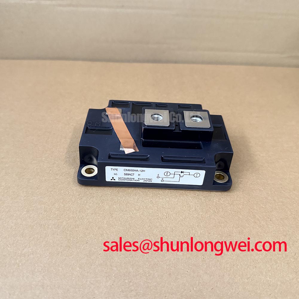
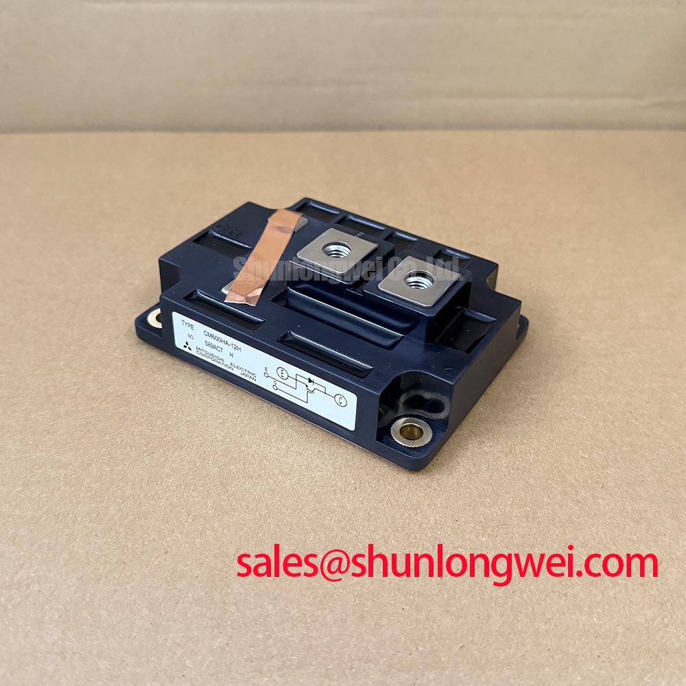
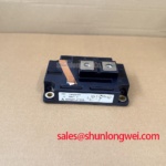
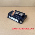
Isolate and discharge the converter DC link, then compare the cold-state collector-to-emitter and gate-to-emitter readings of the installed CM600HA-12H against a known-good phase leg before removing the module. Record the meter polarity and test points so the readings can be repeated after installation. The confirmed product identity is a Mitsubishi Electric IGBT module rated at 600 V and 600 A, both Official Specifications. Those ratings establish an initial screening boundary; they do not establish a drop-in fit for an existing converter.
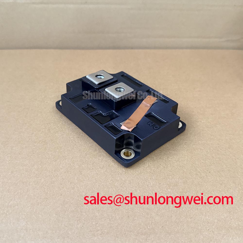
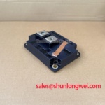
Start the fit check at the terminals. Compare the installed module’s terminal positions, mounting pattern, connection polarity, and available clearance with the proposed CM600HA-12H installation. Confirm the busbar arrangement from the equipment drawing before disturbing it, then photograph the existing gate and power connections. A matching voltage and current rating cannot resolve a mechanical mismatch or an altered current path.
Design Consideration: Where a converter uses parallel IGBT positions, similar busbar path lengths and gate-loop routing can help limit differences in switching behavior. Inspect for loose joints, unequal contact areas, or a gate lead routed differently from its companion positions. Any assumption about static current sharing from a positive temperature coefficient of on-state voltage must be checked against the applicable device characterization; the confirmed specifications provided here do not establish that characteristic or its operating range. Dynamic balance also requires measurement under the equipment’s actual switching conditions.
A multi-megawatt wind turbine full-scale converter is a possible compatibility assessment, not an application approval based on the module rating alone. Compare its DC-link operating range, switching transients, thermal arrangement, and protection scheme with the original equipment documentation. During a parts review, CM100DY-12E can be examined as a separate Mitsubishi Electric module, but its electrical configuration and physical fit must be verified independently; it should not be treated as a confirmed substitute for CM600HA-12H.
CM600HA-12H Thermal-Electrical Optimization: Evaluating Miller Clamp and Gate Supply Behavior
With the DC link isolated, trace the existing gate-driver connections before assigning any switching symptom to the module. Check connector seating, gate-path continuity, and the driver’s specified off-state behavior. A dedicated active Miller clamp, where present in the equipment design, provides a low-impedance path intended to limit unintended gate-voltage rise during rapid collector-voltage transitions. Its suitability depends on the driver circuit, wiring, and measured switching waveforms; it is not a feature established by the confirmed CM600HA-12H ratings.
Design Consideration: If a replacement driver design uses negative gate bias, select and validate that bias from the applicable module and driver documentation rather than assigning a value from a generic IGBT practice. When assessing a bootstrap-powered high-side driver, account for the charge needed to switch the gate, driver quiescent consumption, leakage, and the longest interval before recharge. The required capacitance and allowable voltage droop are system-determined. The confirmed product information does not provide a gate-charge value for a numerical sizing calculation.
If an off-state gate waveform shows an unexpected rise, compare it with the driver command and collector-voltage transition on a known-good leg. That comparison can distinguish a possible gate-drive or layout issue from a module-only assumption. Converter topology matters here: zero-voltage-switching resonant converters and buck converters illustrate different switching and energy-transfer arrangements. Neither reference defines the gate-drive requirements or approved circuit role of this module.
Assembly Integrity and Layout: Assessing Transient Thermal Response
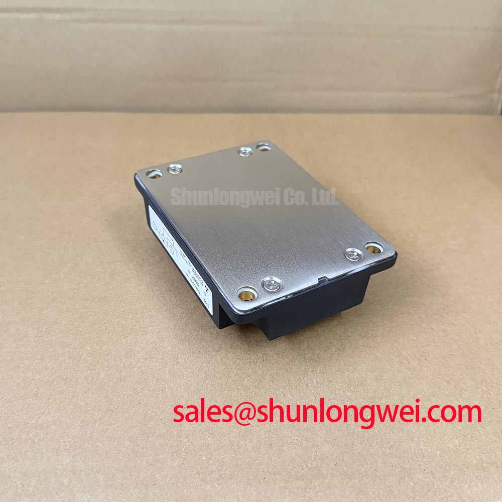
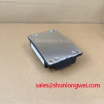
Before reuse or replacement, inspect the heatsink landing area and record the position of any surface marks, residue, or uneven contact pattern. Check that the module can sit without rocking and that attached busbars do not pull its case out of alignment. These observations matter when a converter trips under load: a poor thermal interface, an electrical overload, and a sensing fault can produce overlapping symptoms.
Engineering Recommendation: For pulsed-load assessment, use the manufacturer’s transient thermal-impedance information for the exact device revision and the equipment’s measured current and switching profile. A thermal calculation needs loss data, pulse duration, starting temperature, and a verified heat-flow path before it can establish a junction-temperature margin. The confirmed 600 V and 600 A ratings alone cannot supply that result. Avoid assigning a multi-RC thermal model or a peak junction temperature to CM600HA-12H without supporting device data.
At the system level, compare the original power-stage schematic with the installed module arrangement. A circuit containing CM300DXDX1-24A elsewhere in its power path does not establish that the devices serve interchangeable roles; confirm each position from the schematic and its own specifications. For broader discussion of industrial-drive switching tradeoffs, Unlocking Efficiency in Industrial Drives provides technology context, not evidence that CM600HA-12H uses the technology discussed there.
CM600HA-12H Circuit Protection and Reliability: Restoring Heatsink Contact
Clean and inspect the mating surfaces using the equipment’s service procedure. Apply the specified thermal interface material evenly, seat the module without dragging it across the heatsink, and tighten fasteners in a staged sequence consistent with the module and equipment documentation. Check the resulting contact pattern if the service procedure permits it. A specified paste thickness, baseplate curvature limit, or tightening torque has not been established by the confirmed product information, so none should be treated as a CM600HA-12H factory requirement here.
Field Alert: Do not energize the converter until the mounting fasteners, power terminals, and gate connections have been checked against the equipment procedure.
Before returning the power stage to service, repeat the documented cold-state measurements and compare them with the pre-removal record. Restore the protection wiring, verify sensor and driver connections, and observe the equipment’s prescribed commissioning sequence. If a trip recurs, capture the fault record and relevant waveforms before changing gate-drive or protection settings. That preserves the evidence needed to evaluate the module, its mounting interface, and the surrounding circuit separately.