Content last revised on September 10, 2026
CM75TU-24F Initial Inspection
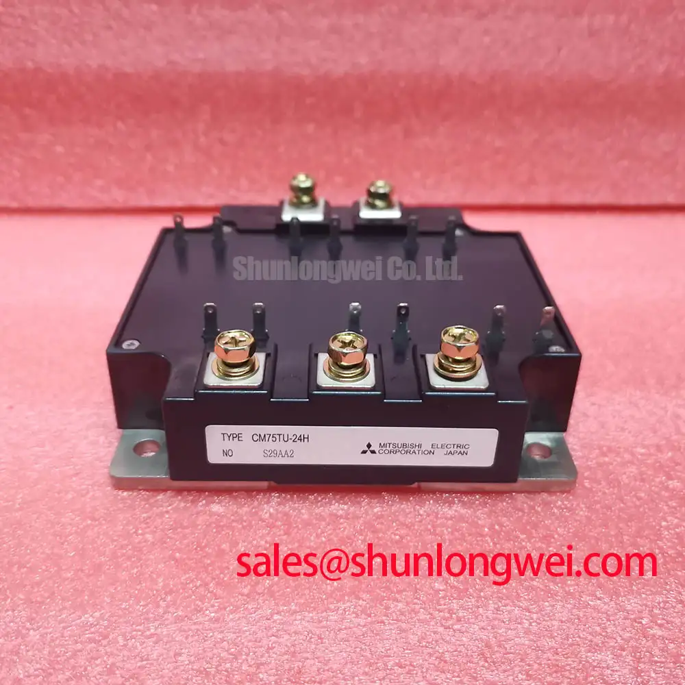
With the drive isolated and the DC link discharged, first compare the cold-state terminal paths of the installed unit against a known-good circuit position before applying gate-drive power. The CM75TU-24F is a Mitsubishi Electric 1200 V, 75 A IGBT module; confirm that these official ratings match the inverter bill of materials and the original drive documentation before considering it for service work.
| Parameter | Official Specification |
|---|---|
| Model | CM75TU-24F |
| Manufacturer | Mitsubishi Electric |
| Voltage Rating | 1200 V |
| Current Rating | 75 A under the specified datasheet conditions |
| Package | Module |
For incoming inspection, use the multimeter diode function only after separating the module from charged capacitors and external parallel paths where practical. Compare the expected diode-direction readings across corresponding power terminals and check that gate-related terminals do not show an unintended low-resistance connection to the power path. A difference from a known-good assembly can indicate a damaged semiconductor path, a board-level parallel component, or an unsuitable test connection, so it should be investigated before assigning a cause.
💡 Bench Tip: Record cold-state diode-mode readings before reconnecting the gate-drive board, and use ESD-safe handling whenever the control terminals are exposed.
Benchtop Waveform Tuning: Mitigating Stress via High-Altitude Cosmic Ray Induced SEB Failure on CM75TU-24F
The CM75TU-24F has an official 1200 V voltage rating, but that rating alone does not establish a site-specific cosmic-ray or single-event burnout performance level. No FIT rate, altitude derating curve, neutron-flux limit, or SEB qualification result should be inferred without the applicable manufacturer documentation and system validation evidence.
At installations above approximately 2000 m, the drive team should treat environmental and insulation coordination review as a Design Consideration. The relevant inspection work is practical: verify enclosure cleanliness, conductor spacing, contamination control, cooling condition, DC-bus transient capture, and the actual switching waveform at the module terminals. Oscilloscope probing must be performed with an appropriate high-voltage differential method and a measurement arrangement that does not add misleading loop inductance.
When intermittent inverter trips occur after relocation or operation at elevation, capture the DC-link voltage, collector-emitter switching waveform, gate-emitter waveform, phase current, and protection response together. A trip event may reflect a control threshold, a supply disturbance, a cable-related transient, or a power-stage condition. Testing the correlated signals is more useful than assuming a single environmental mechanism.
For background on structured power-semiconductor inspection and evidence-based fault isolation, consult the Field Engineer’s Handbook. Mitsubishi Electric’s power semiconductor portfolio information is also an appropriate manufacturer reference point when checking product-family documentation.
Preventing Spurious Faults: Regenerative DC-Bus Voltage Surge Dissipation Guidelines for CM75TU-24F
A regenerating motor can return energy to the DC link during deceleration. The CM75TU-24F must therefore be assessed within the complete inverter arrangement, including the DC-link capacitor bank, braking path, protection thresholds, control timing, cooling system, and mechanical load profile. The module’s official 75 A current rating does not define the safe duty of an external braking transistor, braking resistor, or regenerative supply path.
As an Engineering Recommendation, verify the deceleration event on the actual machine with the intended load condition. Review whether the braking control signal arrives when expected, whether the braking path is electrically continuous, and whether the resistor assembly can dissipate the energy defined by the system’s motion profile. A repeated overvoltage alarm can arise from aggressive deceleration, reduced DC-link capacitance, poor braking-path connection, altered motor inertia, or control configuration differences.
Switching frequency and ambient airflow influence semiconductor and resistor thermal loading. Rather than applying generic frequency limits to this model, the system engineer should compare measured case temperature, heatsink condition, current waveform, and switching behavior with the original equipment requirements. Inspect fan operation, air passages, thermal interface coverage, and the clamping condition between the module base and heatsink. These are Design Considerations, not official CM75TU-24F mounting or thermal ratings.
A metal-oxide varistor or other surge suppression element can be part of a coordinated protection network, but its selection and placement must be verified against the complete DC-bus transient behavior. It should not be treated as a substitute for a correctly functioning braking and control strategy.
Transient Dynamics & Electrical Design: High-Frequency Common-Mode Bearing Current on CM75TU-24F
Long motor cables can behave as transmission lines rather than simple conductors, producing reflected voltage at the motor end and changing common-mode current paths. The CM75TU-24F should be evaluated as part of the inverter output system, not as an isolated explanation for motor bearing symptoms, insulation alarms, or drive trips.
Design Consideration: minimize uncontrolled current loops and verify motor-frame bonding, cable shielding practice, output-reactor placement, filter arrangement, and terminal connections according to the equipment design. An output filter or choke may be evaluated where measured waveforms show reflection-related stress, but its electrical characteristics must be determined by motor-cable length, inverter switching behavior, load requirements, and validated waveform results.
The gate-drive interface also deserves inspection. Optical isolators and digital isolators require a valid power-supply arrangement and correct common-mode transient behavior within the full drive design. Check for distorted gate signals, unexpected gate bias movement, unequal switching timing, or protection signals that occur only during high-current transitions. These observations may indicate layout coupling, isolation-interface behavior, auxiliary-supply disturbance, or controller logic interaction.
For a repair assessment, compare the affected phase with an equivalent healthy phase where the topology permits. Confirm cable termination condition and inspect for loose shielding, damaged motor leads, incorrect phase routing, or changes made during previous service. Do not infer a cable-reflection ratio or filter value from the module rating alone.
Assembly Integrity & Layout Architecture: Implementing High-Frequency Commutation Loop Inductance for CM75TU-24F
Before mounting the CM75TU-24F, inspect the module base, heatsink plane, busbar surfaces, terminal hardware, and insulation interfaces for contamination, burrs, uneven contact, or heat-discoloration evidence. A clean, flat mechanical stack supports repeatable thermal transfer and reduces the chance that tightening variation creates poor electrical contact.
During switching, peak voltage is influenced by DC-link voltage plus the parasitic inductance of the commutation loop multiplied by the rate of current change. This is an Engineering Calculation principle, not an official CM75TU-24F transient limit. The practical layout objective is to minimize the loop area between the DC-link capacitor, power-module terminals, and return conductor so that turn-off inductive overshoot is reduced. The final layout must be verified by switching tests against the DC-link voltage and the applicable device limits.
Use a symmetrical, low-loop-inductance bus structure where the equipment architecture allows it. Keep the DC-link capacitors electrically close to the switching path, avoid unnecessary conductor length, and ensure that power and gate-drive routing do not share uncontrolled return paths. Snubber networks can be evaluated when measured ringing requires damping, yet their capacitance, resistance, voltage capability, and heat dissipation are system-determined values that require bench validation.
For replacement assessment, verify terminal arrangement, control-terminal assignment, mechanical fit, cooling interface, and original drive topology before comparing another module. Where a cross-model engineering review is required, the BSM75GD120DLC can be reviewed as a separate 75 A class module option, subject to full verification of pinout, switching characteristics, mechanical dimensions, protection settings, and original equipment requirements.