
Content last revised on September 10, 2026
Benchtop Waveform Tuning for CR6L 20 UL Output Filter and dv dt Reactor Evaluation
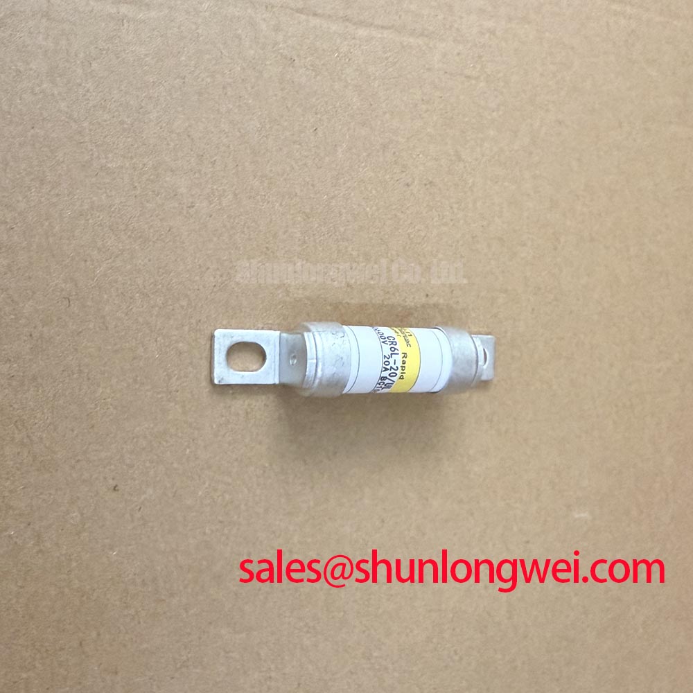
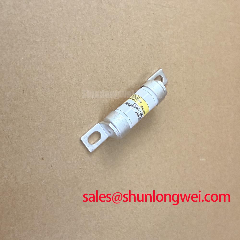
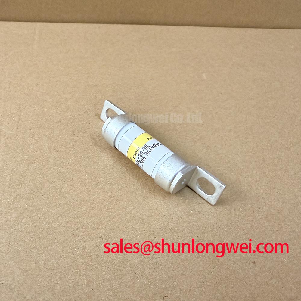
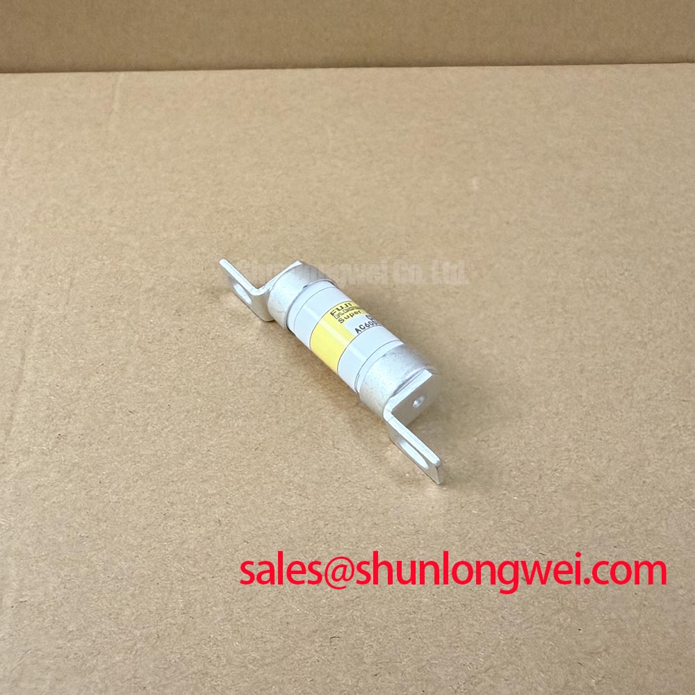
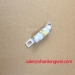
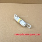
With the drive isolated and discharged, first inspect the CR6L 20 UL fuse body, terminals, holder contact pressure, and adjacent power wiring for heat discoloration, cracking, or loosened hardware before reconnecting the motor circuit. This Fuji Electric High Speed Super Rapid Fuse should be evaluated as part of the complete protection path in a heavy duty variable frequency AC motor drive, rather than as an isolated remedy for waveform problems.
Long motor cables can behave as a transmission path with impedance discontinuities. A steep inverter edge can reflect at the motor end and create terminal excursions that approach twice the inverter step voltage under unfavorable cable and load conditions. This is a system behavior, not a published voltage rating for CR6L 20 UL. The fuse protects against severe overcurrent energy, while output waveform conditioning is determined by the inverter, cable, motor insulation condition, and filter arrangement.
For a suspected cable related event, capture inverter output voltage at the drive end and motor end using appropriately rated differential measurement equipment. Compare phase symmetry, ringing duration, and the timing of protection activity. A sine wave output filter and a dv dt reactor address different conditions. The former is commonly evaluated where the required motor waveform quality is central to the installation; the latter is commonly evaluated where edge rate control and cable related overvoltage reduction are the immediate concerns. This is a Design Consideration; component selection and verification remain system determined.
Desaturation thresholds, collector-emitter saturation measurements, and protection timing must be taken from the applicable drive, IGBT module, and gate-driver documentation. These are diagnostic values for the monitored switching path, not fuse voltage drop ratings. When nuisance trips follow motor lead changes, technicians should compare the sensed waveform and blanking behavior against a known good drive channel before changing protection components.
⚠️ Field Alert: Isolate the DC link and confirm stored energy is discharged before moving motor leads, fuse carriers, or oscilloscope connections.
Assembly Integrity and Layout Architecture for CR6L 20 UL Power Paths
Check that the CR6L 20 UL holder, bus connections, and cable lugs sit flat with no forced alignment from rigid conductors. Uneven contact surfaces can add resistance and localized heating that a visual inspection alone may miss. With power removed, a comparative low resistance measurement across equivalent phase protection paths can help identify a questionable connection, provided probe lead resistance and the measuring method are accounted for.
In an inverter power stage, turn off overshoot is governed by the DC link voltage plus the voltage developed across stray inductance as current changes. This is an Engineering Calculation principle: peak voltage rises with both parasitic loop inductance and switching current slew rate. A planar, symmetrical busbar arrangement is often considered to minimize loop area and reduce unequal phase behavior, but the acceptable result must be established from the actual DC link, gate drive, switching frequency, semiconductor limits, and measured switching waveform.
Fast freewheeling diode recovery can contribute to ringing and radiated disturbance when the commutation path is poorly controlled. Engineers should inspect the physical return path between the DC link capacitor, inverter bridge, fuse assembly, and associated snubber network. Keep high current paths direct, avoid unnecessary conductor separation, and verify with switching tests rather than relying on geometric assumptions. Snubber capacitors can moderate a measured transient, but their value, current capability, placement, and loss budget are system determined.
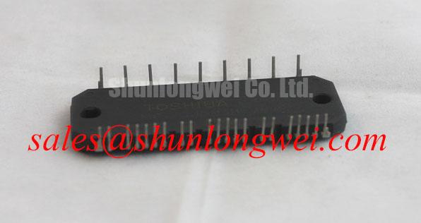
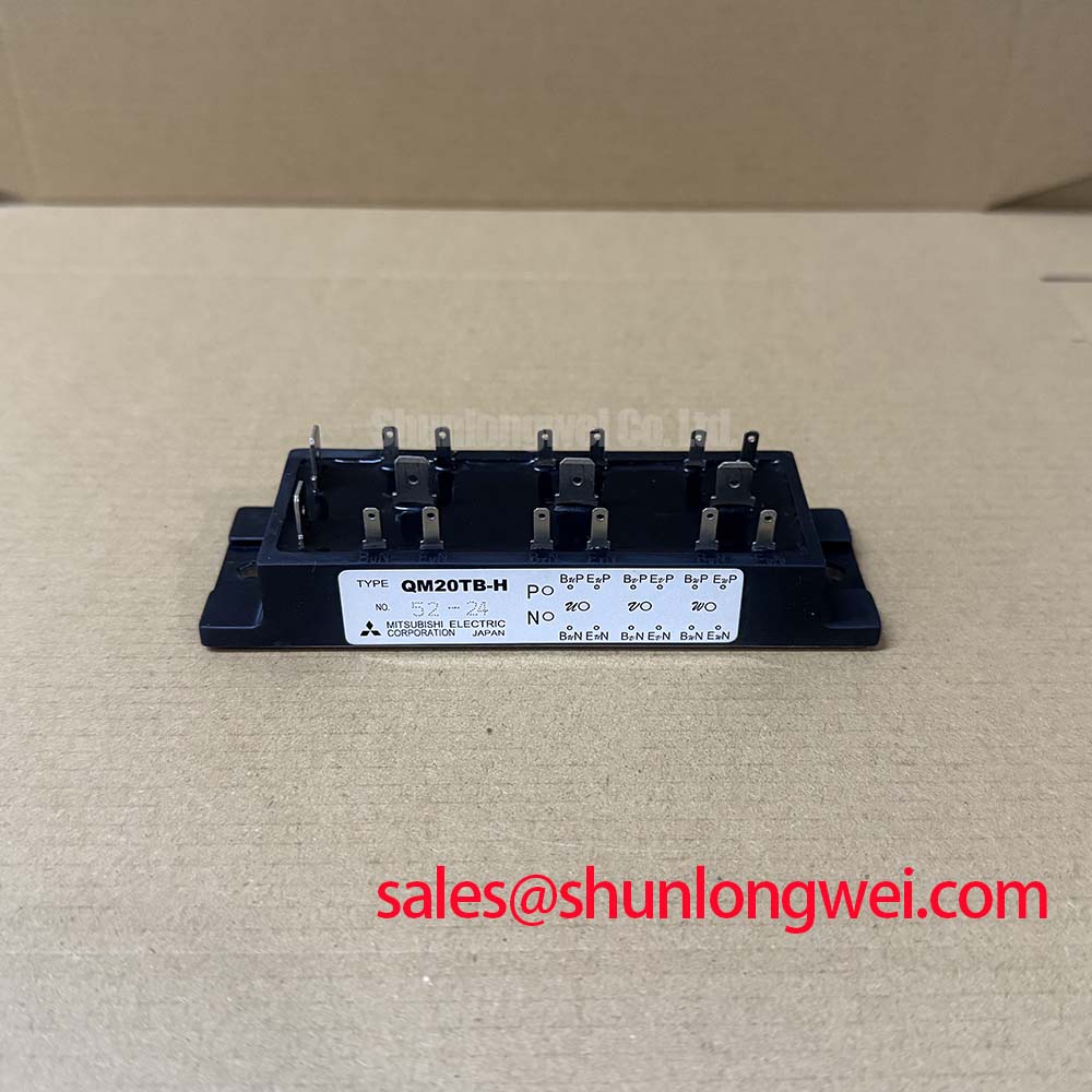
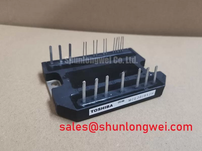
Where replacement planning is being reviewed across a wider power assembly, the 7MBR15PE120 is a separate power module reference that should be compared only against the original circuit topology, electrical ratings, mounting arrangement, and drive interface documentation. It is not an automatic substitute for CR6L 20 UL.
CR6L 20 UL Circuit Protection and Thermal Response Evaluation
After a high current interruption or unexplained drive shutdown, inspect the fuse mounting surfaces and all nearby heat generating connections before returning the machine to service. The CR6L 20 UL is a fast acting protection element, but it does not replace verification of the IGBT thermal path, cooling airflow, heat sink condition, braking circuit, or drive control response.
Desaturation blanking time and short-circuit protection limits are characteristics of the applicable gate driver and power module system, not configurable characteristics of the CR6L 20 UL fuse. When reviewing repeated protection events, check the actual drive documentation and compare the captured gate and collector waveforms with the specified protection behavior.
Gate-driver systems may use standard gate resistor discharge and controlled soft turn-off behavior during a protection event. The applicable timing and resistor values must be verified from the original drive and module documentation rather than inferred from the fuse designation. When a drive has repeated protection events, inspect whether the captured gate and collector waveforms show a controlled response or an abrupt disturbance caused by a wiring, supply, control, or load issue.
Thermal assessment of the semiconductor should use its published transient thermal impedance network and the actual pulse profile. A multi RC thermal model can estimate the path from junction to case during repetitive overload, but measured case temperature, cooling performance, switching loss, conduction loss, and pulse history all affect the outcome. Engineers should validate the peak junction margin under the worst observed duty cycle rather than treating a heat sink temperature as a complete thermal assessment.
A braking chopper and braking resistor may absorb regenerative energy when the motor decelerates or an overhauling load returns energy to the DC link. If fuse operation coincides with braking activity, record DC link behavior, chopper command status, resistor continuity, and the motor deceleration profile. This avoids attributing every DC link event to one device.
For background on the distinction between rapid semiconductor protection and general circuit interruption, consult Semiconductor Fuse High Speed Fuse Protection.
Common Mode Transient Immunity Checks Around CR6L 20 UL Drive Protection
Verify the physical separation and routing of gate drive control wiring before treating a protection trip as a fuse related problem. Inverter switching nodes can impose common mode movement across isolated driver interfaces. If isolation performance is inadequate for the actual installation, spurious gate activity or corrupted desaturation sensing may occur even when the CR6L 20 UL itself remains electrically intact.
A gate-emitter pull-down path can help maintain a defined off-state and reduce floating-gate risk, but its resistance value must be verified from the original gate-driver and power-module documentation. An open or degraded path can create a floating gate risk. With the drive de energized, compare the gate emitter resistance of the affected channel with an undamaged channel where the circuit architecture permits. Do not apply arbitrary drive voltages to an unknown gate circuit during this check.
Isolation barrier voltage capability and common mode transient immunity must be verified from the original driver, isolator, and system documentation. No independent reinforced isolation or common mode transient rating is asserted here for CR6L 20 UL. As a Design Consideration, route sensitive sensing paths away from high dv dt conductors, preserve intended isolation clearances, and confirm the result using differential waveform measurements under controlled switching conditions.
Where a drive redesign is considering upstream rectification or a related power stage, the 6MBI300U-120 provides a separate device reference for objective topology and rating review. Any integration decision should follow the original equipment schematic and measured electrical conditions. For broader context on switching speed, layout sensitivity, and emerging semiconductor technologies, see Wide Bandgap Revolution.