

Content last revised on September 23, 2026
Field Diagnostics & Commissioning: Galvanic Gate Drive Isolation, Reinforced in FB15R06KL4_B1 Topologies
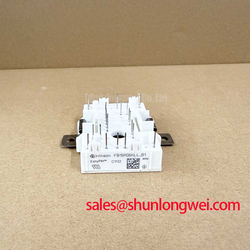
Before energizing a replacement board, compare the cold-state terminal relationships of the installed unit with the circuit schematic and record the module marking as FB15R06KL4_B1. This Infineon power integrated module is rated at VCES = 600 V, with a continuous DC collector current of IC = 15 A at TC = 80°C. Its repetitive peak collector-current rating is ICRM = 30 A for a 1 ms pulse. These are Official Datasheet Specifications and define the electrical identity that should be matched before a repair is commissioned.
| Official Specification | Value and Condition |
|---|---|
| Collector-emitter voltage | 600 V |
| Continuous DC collector current | 15 A at case temperature 80°C |
| Repetitive peak collector current | 30 A for 1 ms |
| Total power dissipation | 85 W per IGBT at case temperature 25°C |
| Gate-emitter peak voltage | ±20 V |
| Isolation test voltage | 2.5 kV RMS, 50 Hz, 1 minute |
Check the gate-driver isolation barrier before connecting the FB15R06KL4_B1 to a live DC link. The module itself carries an Official Datasheet isolation test rating of 2.5 kV RMS for one minute at 50 Hz. This rating should not be confused with the isolation capability of the external gate driver, the PCB barrier, the current sensor, or any control-side communication interface.
A reinforced galvanic isolation claim for a complete gate-drive topology must be verified from the driver and system documentation. Likewise, common-mode transient immunity is a driver-level characteristic rather than a published FB15R06KL4_B1 module rating. As a Design Consideration, technicians should inspect the isolation barrier, connector condition, gate-drive supply reference, and PCB clearance around high-voltage nodes when unexplained gate pulses appear during switching tests.
With the DC link discharged, use a multimeter diode function only as a comparative incoming check. Compare corresponding power-terminal readings with a known-good board or documented circuit path, and verify that gate terminals are not shorted to the associated power terminals. A diode reading alone does not establish the module pin assignment or prove dynamic switching health. Confirm the terminal map from original equipment documentation before applying any gate signal.
💡 Bench Tip: Keep the gate terminals protected from electrostatic discharge and make all cold-state comparisons with the same meter polarity, test leads, and reference board condition.
For equipment repair teams assessing broader isolation, transient, and fault-investigation practices, the Field Engineer’s Handbook provides a useful technical reference point. It should support, rather than replace, the original inverter manufacturer’s commissioning sequence.
Transient Dynamics & Electrical Design: High-Speed Fault Management: VCE Desaturation on FB15R06KL4_B1
Desaturation protection should be evaluated as part of the gate-driver assembly, not assigned to the FB15R06KL4_B1 itself. The module’s 600 V collector-emitter voltage rating establishes an official blocking limit, while a desaturation circuit observes switching behavior externally and can initiate controlled shutdown when a fault condition is detected. The protection threshold, blanking interval, sensing network, and soft-turn-off behavior are system-determined and require validation against the actual bus voltage, wiring inductance, load path, and driver data.
Short-circuit detection must be coordinated with the safe operating limits supplied for the installed topology. A two-stage turn-off approach is often considered where rapid gate removal could create a damaging inductive voltage excursion. This is an Engineering Recommendation rather than an official setting for this module. Oscilloscope measurements at the module terminals should verify collector-emitter voltage behavior and gate response during controlled commissioning, using properly rated differential measurement equipment.
Where parallel devices are being considered, identical part numbers alone do not guarantee equal current distribution. Static sharing can be influenced by device voltage characteristics, temperature, conductor resistance, and busbar symmetry. A positive temperature coefficient in the relevant operating region can assist sharing, but it does not remove the need for matched physical current paths and measured validation. Avoid treating the 15 A continuous rating as a simple multiplier when parallel paths have unequal cooling or unequal switching loops.
For a separate system topology review, engineers may compare interface requirements with devices such as FS100R12N2T4. Such a comparison should cover voltage class, current capability, terminal arrangement, gate-drive compatibility, thermal interface, and protection coordination; it is not a statement of interchangeability.
FB15R06KL4_B1 Thermal-Electrical Optimization: Kelvin Emitter Connection Practical Tuning
The FB15R06KL4_B1 has an Official Datasheet total power dissipation rating of 85 W per IGBT at TC = 25°C. This number is a specified thermal boundary under its stated condition, not a guaranteed dissipation allowance for an assembled inverter. Actual thermal performance depends on the heatsink interface, mounting pressure, airflow, switching loss, conduction loss, ambient conditions, and the thermal path through the equipment enclosure.
Before assuming a Kelvin-emitter arrangement, verify the available terminals from the original module documentation and PCB artwork. If a dedicated auxiliary emitter connection exists in the installed circuit, a Design Consideration is to keep the gate-drive return separated from the high-current emitter path as far as the physical layout permits. This reduces shared inductive voltage in the gate loop and can help prevent unwanted oscillation during high di/dt transitions. If no auxiliary emitter terminal is present, the existing gate-return routing and power-emitter path should be inspected as a coupled system.
Thermal checks should begin with practical observations: inspect the contact surface, verify that the heatsink is flat and clean, and confirm that mounting hardware is tightened according to the equipment manufacturer’s assembly requirement. During a controlled load test, compare case temperatures and switching waveforms with known-good equipment where available. A rising temperature trend may involve the cooling system, interface quality, load duty, gate behavior, or DC-link conditions, so it should not be attributed to one cause without measurement.
Infineon’s discussion of TRENCHSTOP™ IGBT7 module technology offers useful industry context on module-level thermal and reliability development. It does not establish an unpublished structural or thermal parameter for the FB15R06KL4_B1.
FB15R06KL4_B1 Operational Boundaries: Evaluating Bi-Directional DC-DC Buck-Boost Conversion Limits
In commercial string inverter and micro-grid energy-storage equipment, a bidirectional DC-DC stage can transfer energy between battery racks and an inverter DC link. Engineers evaluating the FB15R06KL4_B1 for this role should first verify that the topology’s maximum voltage remains within the official 600 V VCES rating under normal operation, regenerative events, switching transients, and protection activity. The actual operating margin is determined by the complete system and must be confirmed through measurement.
Repeated charge and discharge cycles can produce changing current direction, varying switching duty, and thermal swings. The official 15 A continuous current rating at 80°C case temperature remains condition-specific; it does not by itself confirm suitability for a particular battery peak-shaving profile. Designers should assess junction-temperature behavior using the applicable manufacturer thermal data, measured case conditions, and the real current waveform rather than relying on nominal battery current alone.
Reverse-conducting behavior must also be understood from the actual converter commutation path. The external reference Infineon RCDC application note explains general reverse-conducting IGBT considerations. It should not be used to infer unlisted reverse-conduction characteristics for this specific product.
When a repair evaluation requires comparison with another power module, BSM100GAL100D can be reviewed as a separate device option. Any substitution decision requires documented verification of electrical ratings, control topology, mechanical fit, isolation requirements, and thermal behavior within the original equipment.