Content last revised on October 29, 2026
Turn-Off Voltage Peaks and Busbar Layout for FF400R12KL4C
A converter fault recorded during turn-off deserves a waveform check before the module is blamed. In a switching loop, stray inductance adds a transient voltage to the DC-link voltage as current changes. As an Engineering Calculation, the first-order relationship is that peak voltage is approximately DC-link voltage plus loop inductance multiplied by the rate of current change. It explains why a module can encounter a higher instantaneous voltage than a steady DC-link reading suggests; it does not establish a permissible peak for this installation.
For the FF400R12KL4C, compare measured switching peaks with its 1200 V blocking rating (Official Specification) and the applicable limits in the complete manufacturer documentation. Capture the waveform at a suitable point in the installed circuit using appropriately rated measurement equipment. Note the load, DC-link condition and gate-drive state alongside the trace. A fault log alone cannot distinguish an overvoltage event from a sensor or protection-circuit response.
As a Design Consideration, keep the outgoing and return current paths close together and place any specified snubber connection where it can act on the relevant switching loop. These measures can reduce parasitic inductance and turn-off overshoot, but busbar geometry, electrical clearances and snubber selection must be validated in the actual converter. Do not assign a snubber capacitor value from the 1200 V and 400 A ratings alone; switching energy, layout and thermal conditions also matter.
If a replacement is being evaluated rather than a like-for-like fit, the FZ3600R12HP4 offers a separate model page for a documented specification comparison. Its part number does not establish electrical or mechanical equivalence to FF400R12KL4C. Check the original schematic and assembly drawing before treating any other module as a candidate.
Field Diagnostics and DC-Link Voltage Headroom
When commissioning or investigating an intermittent trip, record the DC-link voltage under the conditions that produce the event, then compare it with a switching capture and the protection-system log. The 1200 V rating (Official Specification) is the module’s stated blocking-voltage rating, not a stand-alone approval for a particular DC-link setting. Allowance for measured overshoot and operating variation is a system-design decision.
As a Design Consideration, environmental conditions and voltage stress should be reviewed together when assessing a converter installation. Cosmic-ray-related single-event effects and altitude-dependent exposure are specialist reliability topics; the supplied product specifications do not provide a failure-in-time rate, an altitude derating curve or a lifetime prediction for FF400R12KL4C. A site-specific conclusion would require applicable manufacturer reliability information and a defined operating profile. It would be misleading to turn the module’s voltage rating into an unsupported failure-rate estimate.
For a potential multi-megawatt wind-turbine full-scale converter application, first confirm whether the existing equipment uses this exact module and whether its cooling, gate drive and fault thresholds match the original design. That equipment type is a compatibility example, not a stated intended application or a guarantee of suitability. During field checks, inspect accessible busbar joints and snubber connections for looseness, discoloration or damage, then relate any finding to measured electrical behavior rather than assuming one visible condition explains every trip.
Product-family distinctions matter during that assessment. Infineon’s Intelligent Power Modules describe a different category in which integration features affect system interfaces. Its automotive-qualified IGBT portfolio is likewise not evidence that FF400R12KL4C carries an automotive qualification. Use the documentation for the exact ordered part when qualification or environmental requirements govern a repair.
Negative Gate Bias, Miller Clamping and Switching Checks
Inspect the installed gate-drive arrangement before changing an IGBT module or adjusting its drive. A rapid voltage change on one switch can couple through gate-to-collector capacitance and disturb the gate of an adjacent switch. Depending on the circuit, a negative off-state gate bias or an active Miller clamp can help hold that device off. Neither measure can be prescribed solely from the FF400R12KL4C model number and its headline ratings.
As a Design Consideration, verify the existing driver’s off-state behavior against its schematic while preserving the original protection functions. Check gate and emitter connections, driver supply behavior and the switching waveform under controlled commissioning conditions. If an unexpected gate excursion appears, compare it with a known-good phase where available; inspect the driver path and nearby switching loop before attributing the event to the module. Any change to bias or clamping should be assessed against the module’s complete gate limits and demonstrated in the actual converter.
The Evolution of Negative Off-Bias Gate Drive Circuits provides background on the tradeoffs between off-state bias arrangements. It is a circuit-design reference, not an FF400R12KL4C gate-voltage specification. During maintenance, preserve the routing and connection order documented for the installed driver: a plausible-looking connection is not enough to establish the correct gate-drive path.
Maintenance note: Verify that the DC link is discharged before handling module terminals or gate-drive connections.
Heatsink Contact and Mounting Checks for FF400R12KL4C
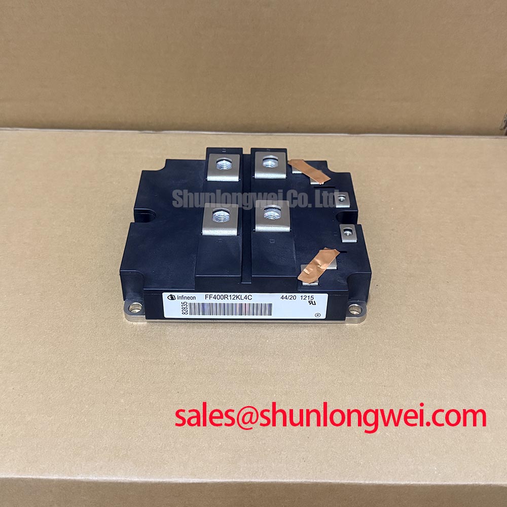
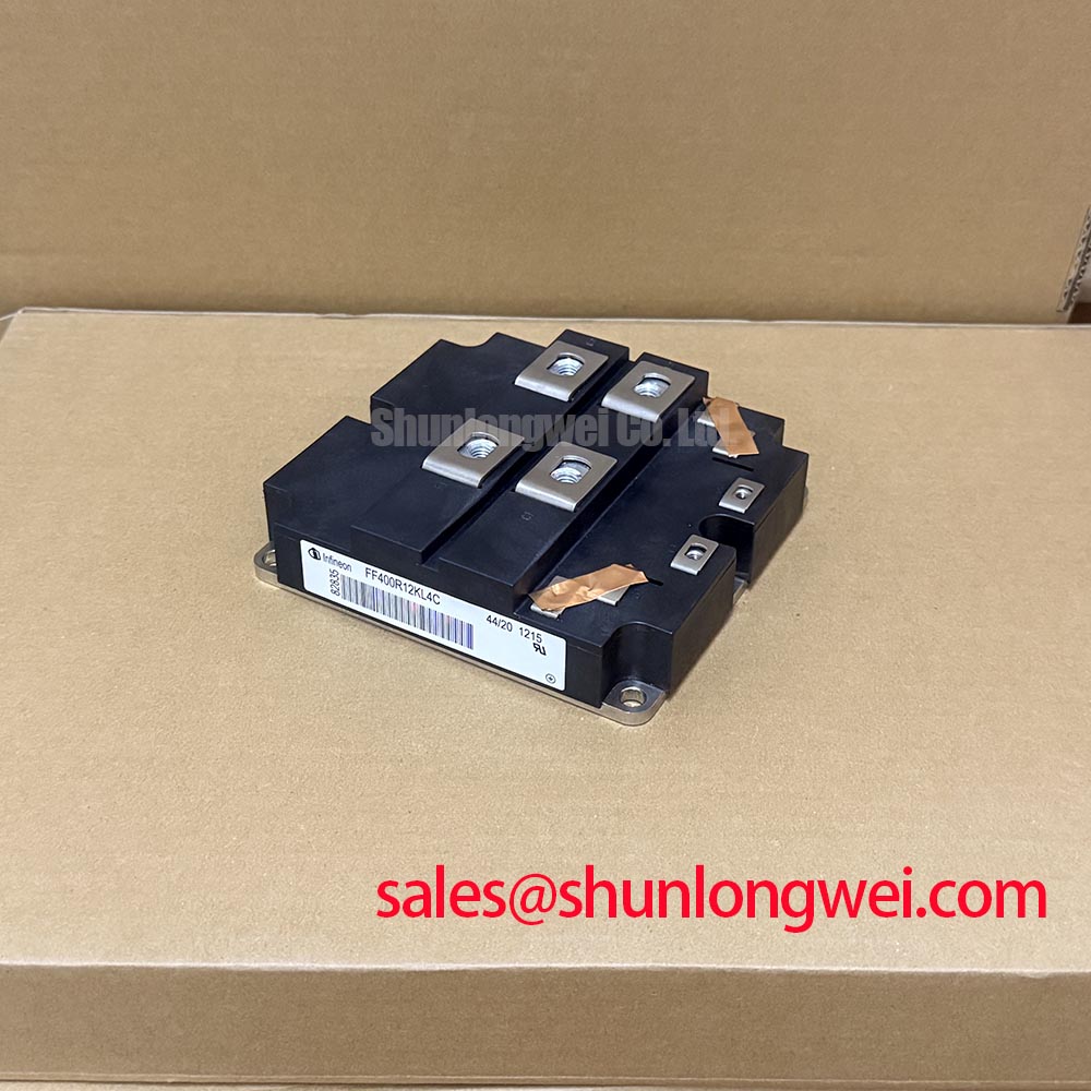
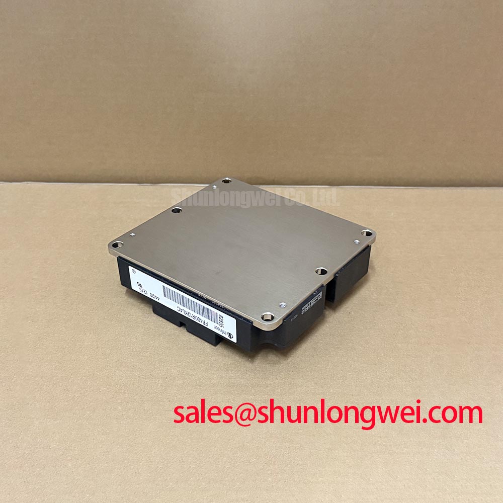
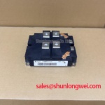
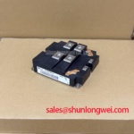
Before mounting the FF400R12KL4C, examine the heatsink contact area for debris, raised damage, corrosion and remnants of old thermal interface material. Check the module’s mating surface and the equipment’s mounting drawing without assuming that a surface defect can be corrected by tightening the fasteners further. Contact quality depends on the assembled surfaces, the specified interface material and the prescribed fastening procedure.
As a Design Consideration, apply thermal interface material consistently to avoid obvious gaps or excess buildup, and follow the original equipment or module documentation for preparation, fastening sequence and torque. No interface thickness or screw torque is established by the supplied product specifications, so a generic workshop value must not be presented as an Infineon requirement for this module. If the mounting hardware, heatsink or interface material has changed, confirm the applicable procedure before energizing the converter.
For preventive maintenance, inspect the heatsink airflow path for dust accumulation and compare operating temperature trends under comparable loads. Review accessible power-terminal joints using the equipment maker’s inspection and tightening procedure. Condensation or moisture around the assembly calls for an enclosure and environmental-control check before operation; the Module package designation (Official Specification) does not establish protection against those conditions.
If temperatures rise after service, work through the evidence in order: confirm fan or coolant operation, inspect airflow restrictions, review load history, and check the mounting record and measured thermal behavior. A hot heatsink, a protection trip or a changed temperature trend can have more than one cause. Resolving which one applies to the installed FF400R12KL4C requires comparison with the converter’s documented baseline and its actual operating conditions.