

Content last revised on May 3, 2026
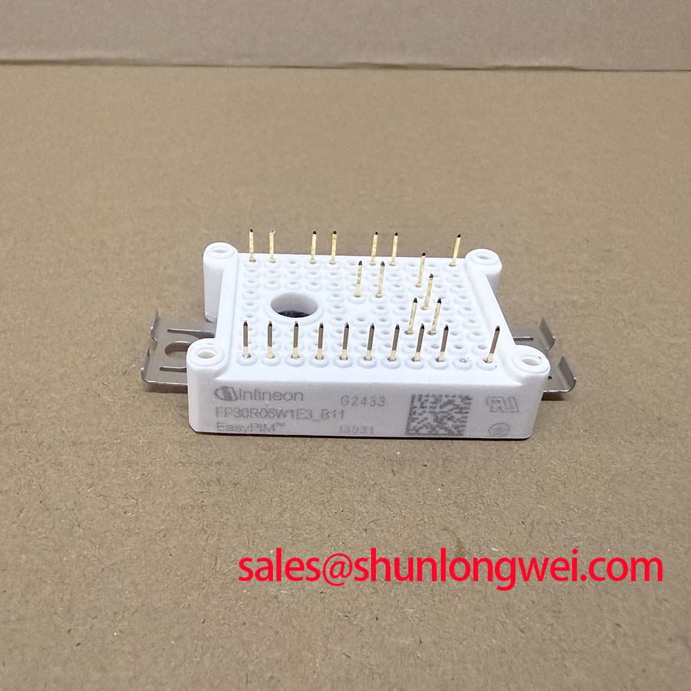
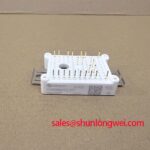
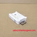
FP30R06W1E3_B11 IPM: Integrated 600V/30A 3-Phase Module
Streamlining Motor Drive Design and Assembly
Imagine reducing your motor drive's PCB complexity and assembly time simultaneously. The Infineon FP30R06W1E3_B11 Intelligent Power Module is engineered to achieve precisely that, simplifying the entire power stage design for low-power applications. This module streamlines development through superior integration and solderless PressFIT assembly, enabling faster manufacturing cycles. For engineers asking how to simplify inverter design, this IPM integrates key functions like bootstrap diodes and an NTC, while its PressFIT pins eliminate the entire soldering step for the power module.
Top Specs: 600 V | 30 A | TRENCHSTOP™ IGBT3
Key Benefits:
- Reduced external component count.
- Accelerated, solder-free manufacturing.
Core Specifications for Simplified Integration
The technical parameters of the FP30R06W1E3_B11 are tailored for compact and efficient motor drive systems. The specifications below are grouped by function to facilitate a clear evaluation for your design. For a complete list of parameters, please refer to the official datasheet.
| Parameter | Condition | Value |
|---|---|---|
| Inverter Stage Electrical Characteristics | ||
| Collector-Emitter Voltage (V_CES) | T_vj = 25 °C | 600 V |
| Continuous Collector Current (I_C) | T_C = 80 °C, T_vjmax = 175 °C | 30 A |
| Collector-Emitter Saturation Voltage (V_CEsat) | I_C = 30 A, T_vj = 25 °C | 1.50 V (typ.) |
| Total Switching Energy (E_tot) | I_C = 30 A, V_CE = 300 V, V_GE = ±15 V, R_G = 22 Ω, T_vj = 125 °C | 3.20 mJ (typ.) |
| Thermal and Mechanical Characteristics | ||
| Thermal Resistance, Junction-to-Case | per IGBT | 1.4 K/W (max.) |
| Operating Junction Temperature | - | -40 to +150 °C |
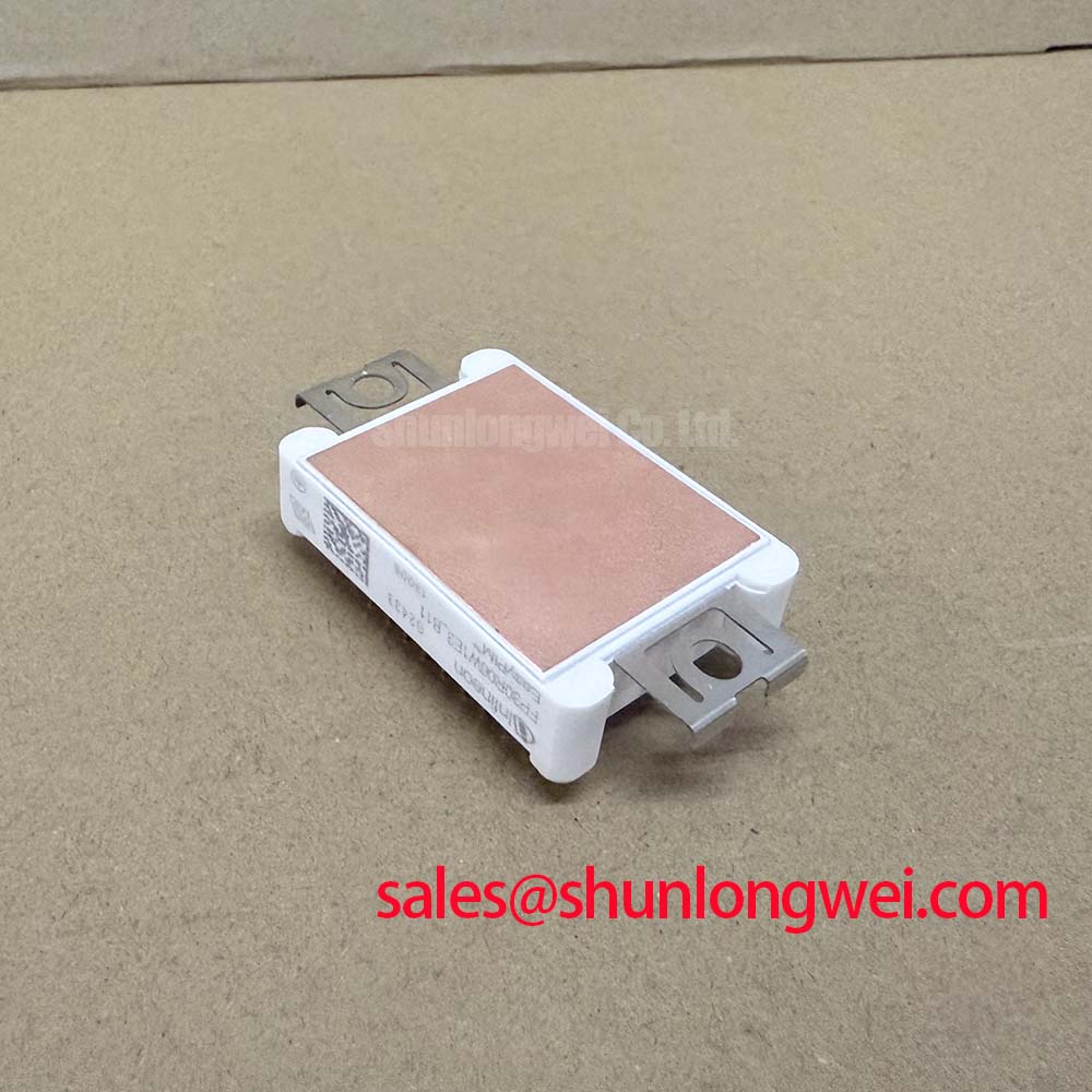
| Housing | - | EasyPACK™ 1B |
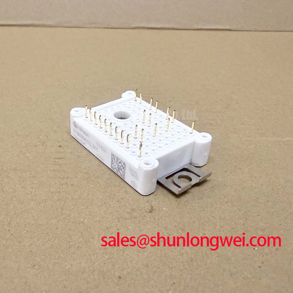
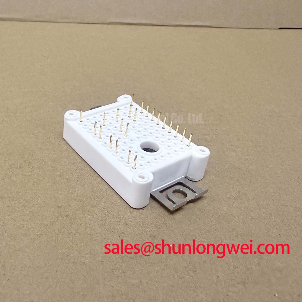
| Mounting Technology | - | PressFIT |
| Integrated Features | ||
| Temperature Sensor | - | NTC Thermistor |
| Bootstrap Function | - | Integrated Diodes & Resistors |
Interpreting Key Parameters for Your Design
Understanding the engineering value behind the numbers is crucial for component selection. Here are insights into two critical specifications:
- Collector-Emitter Saturation Voltage (V_CEsat): With a typical value of 1.50V at nominal current, this parameter directly influences conduction losses. A lower V_CEsat acts like a wider, less restrictive channel for current flow, minimizing the energy wasted as heat. This is fundamental for achieving high efficiency and simplifying thermal management, particularly in space-constrained or fan-less designs.
- Integrated Bootstrap Function: The inclusion of bootstrap diodes and resistors within the module is a cornerstone of its design simplification value. This feature provides the necessary floating power supply for the high-side gate drivers, eliminating the need for several external components. For designers, this translates directly to a smaller PCB footprint, a reduced Bill of Materials (BOM), and a less complex layout process.
Deployment Focus: Accelerating Assembly with PressFIT
Consider a manufacturer of high-volume home appliance motor controllers facing a production bottleneck due to the time-intensive process of soldering power modules. By adopting a component like the Infineon FP30R06W1E3_B11 with its PressFIT technology, the assembly process shifts from soldering to a simpler, faster press-in operation. This change can significantly increase manufacturing throughput. More importantly, it eliminates solder-joint-related field failures, enhancing the product's long-term reliability and potentially reducing warranty costs associated with thermal cycling fatigue.
Optimized Applications: Where Integration Delivers Value
The FP30R06W1E3_B11 is engineered for applications where a compact footprint, manufacturing efficiency, and operational reliability are key design drivers. Its integrated nature provides tangible benefits across several sectors.
Primary Application Areas
- Home Appliances: Ideal for the inverters in modern washing machines, air conditioners, and refrigerators, where space is limited and cost-effective, high-volume manufacturing is essential.
- Low-Power Motor Drives: Excellently suited for general-purpose industrial drives, servo drives for automation, and other variable-speed motor applications requiring high efficiency and a streamlined design.
- Fans and Pumps: Provides a compact and reliable power stage for HVAC systems and industrial fluid handling, where dependable, long-term operation is critical.
What is the main benefit of the integrated NTC? It provides direct thermal feedback for precise system protection. How does PressFIT technology simplify manufacturing? It enables reliable, solder-free mounting, reducing assembly time and cost. For low-power drives up to approximately 2.2 kW where reducing BOM count and assembly complexity is paramount, this IPM's integrated features provide a clear design advantage.
Strategic Advantage in Modern Drive Design
The features within the FP30R06W1E3_B11 align with key industrial and consumer market trends. The global push for greater energy efficiency in appliances, driven by standards like Energy Star, necessitates highly optimized power stages. The module's use of Infineon TRENCHSTOP™ IGBT3 technology provides a well-balanced performance between conduction and switching losses, contributing directly to these efficiency goals. Furthermore, the increasing automation in manufacturing favors components that simplify assembly. PressFIT technology directly supports this trend, offering a path to create competitive products with a more efficient and reliable production line.
Data for Decision-Making: A Factual Comparison
To assist in your evaluation process, the following table presents a factual comparison between the FP30R06W1E3_B11 and another module with a different voltage class. This data is intended to empower your technical decision-making based on specific system requirements, such as DC bus voltage and power level.
| Feature | FP30R06W1E3_B11 | FP35R12W2T4 |
|---|---|---|
| Voltage Class (V_CES) | 600 V | 1200 V |
| Nominal Current (I_C) | 30 A | 35 A |
| Configuration | Three-Phase Inverter | Sixpack |
| Mounting Technology | PressFIT | Solder Pin |
| Primary Application Focus | Low-voltage motor drives, appliances | Higher voltage industrial drives |
For systems operating on a higher DC bus (e.g., derived from 400/480 VAC lines), a module like the FP35R12W2T4 offers the necessary 1200V blocking voltage capability.
A Closer Look at the Integrated Architecture
The performance of the FP30R06W1E3_B11 is rooted in its advanced semiconductor technology and intelligent package design. The TRENCHSTOP™ IGBT3 technology is engineered to offer an optimal balance between low conduction losses (V_CEsat) and minimal switching losses. This equilibrium is particularly effective for motor drive applications that typically operate at switching frequencies between 5 kHz and 20 kHz. The co-packed Emitter Controlled diodes are optimized with a low forward voltage drop and soft recovery behavior, which helps to reduce IGBT turn-on losses and mitigate electromagnetic interference (EMI). This comprehensive approach to integration simplifies the power stage and enhances overall system performance. For further reading, an in-depth analysis of IGBT Modules can provide additional context.
Frequently Asked Questions
1. What are the primary considerations when designing a PCB for the FP30R06W1E3_B11's PressFIT pins?
The most critical factors are the specifications for the plated through-holes (PTH). The official datasheet provides precise requirements for the finished hole diameter, copper plating thickness, and annular ring. Adherence to these tolerances is vital. Additionally, using the manufacturer-recommended press-in tool is essential to form a reliable, gas-tight cold-weld connection without exerting excessive stress on the PCB or the module itself.
2. Does the integrated bootstrap function have any limitations?
Yes, a bootstrap power supply architecture depends on the periodic switching of the low-side IGBT to recharge the external bootstrap capacitor. In operating modes where a high-side IGBT must remain continuously on for an extended duration (approaching 100% duty cycle), the capacitor will eventually discharge, leading to an insufficient gate voltage for the high-side switch. System designers must account for this by ensuring a minimum low-side on-time or implementing an alternative power supply if such static high-side-on conditions are required.
Your Next Steps
To evaluate how the FP30R06W1E3_B11 can streamline your next motor drive design, review the detailed electrical and thermal characteristics in the official datasheet. For technical inquiries regarding system integration, PCB layout best practices, or thermal modeling, our team is available to provide the necessary documentation and support your engineering process.