


Content last revised on May 27, 2026
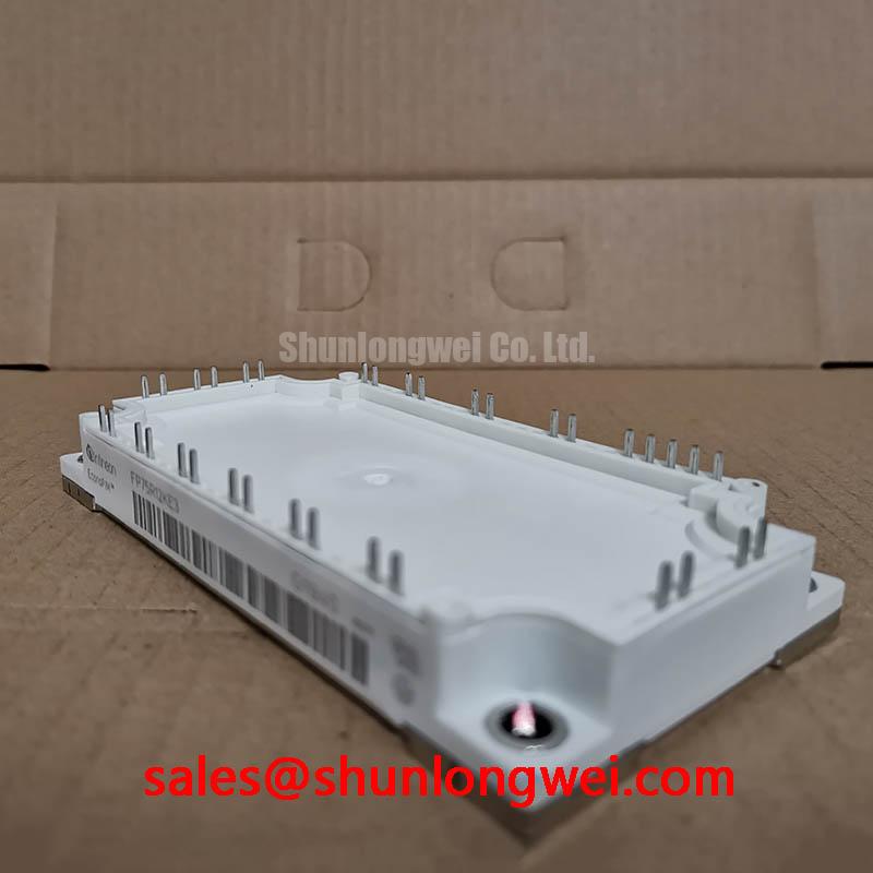
FP75R12KE3 IGBT Module: Engineering Insights for High-Efficiency Power Conversion
A Datasheet-Driven Analysis of the 1200V, 75A Six-Pack Module
Executive Summary: Performance and Efficiency
Engineered for superior performance in demanding power conversion systems, the FP75R12KE3 is a highly integrated Six-Pack IGBT module from Infineon. It delivers a robust specification of 1200V and 75A, optimized for high-frequency switching applications. This module's core value lies in its integration of TRENCHSTOP™ IGBT3 technology, which drastically reduces both switching and conduction losses. For engineers designing compact and efficient Variable Frequency Drive (VFD) systems, this translates directly into lower thermal management costs and enhanced system reliability. Best Fit: For motor drives up to 30 kW requiring high switching frequencies to improve motor performance and reduce audible noise, the FP75R12KE3 provides an optimal balance of efficiency and thermal stability.
Application Scenarios & Value
System-Level Benefits in Variable Frequency and Servo Drives
The FP75R12KE3 is primarily designed for the rigorous demands of industrial motor drives, servo drives, and other three-phase inverter applications. A common engineering challenge in modern VFD design is increasing the switching frequency to achieve smoother motor torque, reduce audible noise, and shrink the size of magnetic components. However, higher frequencies typically lead to prohibitive switching losses and thermal stress. This is where the FP75R12KE3 excels.
Its foundation on TRENCHSTOP™ IGBT3 and Emitter Controlled 3 diode technology directly addresses this challenge. The low switching energy (Ets) of 6.50 mJ allows designers to push frequencies higher than possible with older IGBT generations without a significant efficiency penalty. This enables the development of more compact, acoustically quieter, and responsive drive systems that can meet stringent efficiency standards. The module's integrated NTC thermistor further supports system reliability by providing a direct feedback loop for thermal monitoring, a critical feature for compliance with standards like IEC 61800-5-1.
For systems with different power requirements, related modules offer alternative ratings. For lower-power applications, the FP50R12KE3 provides a 50A solution in the same family, while for designs needing increased current handling, the FP100R12KT4 offers a 100A rating.
Key Parameter Overview
Decoding Key Specifications for Performance Optimization
The technical specifications of the FP75R12KE3 are a direct reflection of its intended high-performance applications. The parameters listed below are critical for accurate system modeling, thermal design, and performance prediction. Understanding these values is the first step in leveraging the module's full potential.
| Parameter | Symbol | Condition | Value |
|---|---|---|---|
| Collector-Emitter Voltage | V_CES | T_vj = 25 °C | 1200 V |
| Continuous Collector Current | I_C nom | T_C = 100 °C, T_vj max = 175 °C | 75 A |
| Collector-Emitter Saturation Voltage | V_CE sat | I_C = 75 A, V_GE = 15 V, T_vj = 25 °C | 1.70 V (typ.) |
| Total Switching Energy | E_ts | I_C = 75 A, V_CE = 600V, V_GE = ±15V, R_G = 10 Ω, T_vj = 125 °C | 6.50 mJ (typ.) |
| Thermal Resistance, Junction to Case | R_thJC | per IGBT | 0.27 K/W |
| Short Circuit Withstand Time | t_PSC | V_GE ≤ 15 V, V_CC = 800 V, T_vj max = 150°C | 10 µs |
This table presents a selection of key parameters. For a comprehensive overview, including characteristic curves and application notes, please refer to the official documentation.
Download the FP75R12KE3 datasheet for detailed specifications and performance curves.
Technical Deep Dive
A Closer Look at TRENCHSTOP™ IGBT3 for Reduced System Losses
The performance of the FP75R12KE3 is fundamentally enabled by its semiconductor technology. What is the key benefit of the TRENCHSTOP™ IGBT3 technology? It significantly reduces both conduction and switching losses. The "trench" structure creates a vertical gate, allowing for a much higher density of cells in the silicon compared to older planar IGBT designs. This architectural advantage leads to a lower collector-emitter saturation voltage (V_CE(sat)). Think of V_CE(sat) as the electrical "friction" the device presents when it's fully on. A lower V_CE(sat), like the 1.70V typical value for this module, is akin to a wider, smoother pipe allowing water to flow with less pressure drop—meaning less energy is wasted as heat during conduction.
Equally important is the module's dynamic performance. The combination of the TRENCHSTOP™ IGBT and the Emitter Controlled 3 freewheeling diode is engineered for soft switching behavior. This minimizes voltage overshoots and oscillations during turn-off, which in turn reduces electromagnetic interference (EMI). Lower EMI simplifies the design and cost of system-level filtering, helping to reduce Total Harmonic Distortion (THD) on the output. Switching loss itself can be compared to a sticky light switch; every time you flip it, a small amount of energy is wasted as heat and sound. The fast, clean switching of the FP75R12KE3 is like a well-oiled switch, minimizing that waste with every single cycle, a crucial factor when operating at tens of thousands of cycles per second. For an in-depth guide on these parameters, see this resource on decoding IGBT datasheets.
Frequently Asked Questions (FAQ)
How does the low VCE(sat) of the FP75R12KE3 impact the thermal design of an inverter?
The low typical V_CE(sat) of 1.70V directly reduces conduction power loss (P_cond = V_CE(sat) * I_C). This means less heat is generated for a given current, allowing for the use of smaller, more cost-effective heatsinks or enabling higher power output within an existing thermal envelope. This is a critical factor for increasing the power density of the final product.
What is the primary advantage of the Emitter Controlled 3 diode used in this module?
The Emitter Controlled 3 diode is optimized for soft recovery characteristics. This means it turns off smoothly with low peak reverse recovery current (I_rrm). The engineering benefit is twofold: it reduces switching losses within the diode itself and significantly lowers the voltage stress and EMI generated during the IGBT turn-on event, leading to a more robust and electrically quieter system.
How should the integrated NTC thermistor be utilized in a drive system?
The NTC thermistor provides a real-time temperature reading of the module's baseplate. This data should be fed into the system's microcontroller to implement over-temperature protection. It can trigger alarms, de-rate the output current, or initiate a safe shutdown if the module exceeds its safe operating temperature, drastically improving long-term system reliability and preventing catastrophic failures.
Is the FP75R12KE3 suitable for hard-switching and resonant topologies?
While the low switching losses from the TRENCHSTOP™ IGBT3 technology make it highly efficient in standard hard-switching PWM inverters, its fast and soft freewheeling diode also makes it a viable candidate for certain soft-switching or resonant topologies where controlled switching is paramount.
Strategic Outlook
The FP75R12KE3 represents a strategic choice for designers aiming to create next-generation power electronics that are not only powerful but also highly efficient and compact. As industry regulations for energy consumption become more stringent and market demands for smaller, quieter systems grow, leveraging advanced semiconductor technologies like TRENCHSTOP™ IGBT3 is no longer an option but a necessity. This module provides the foundational building block to meet these future challenges, offering a clear path to enhanced performance and competitive advantage in the industrial drive and power conversion markets.