Content last revised on May 26, 2026
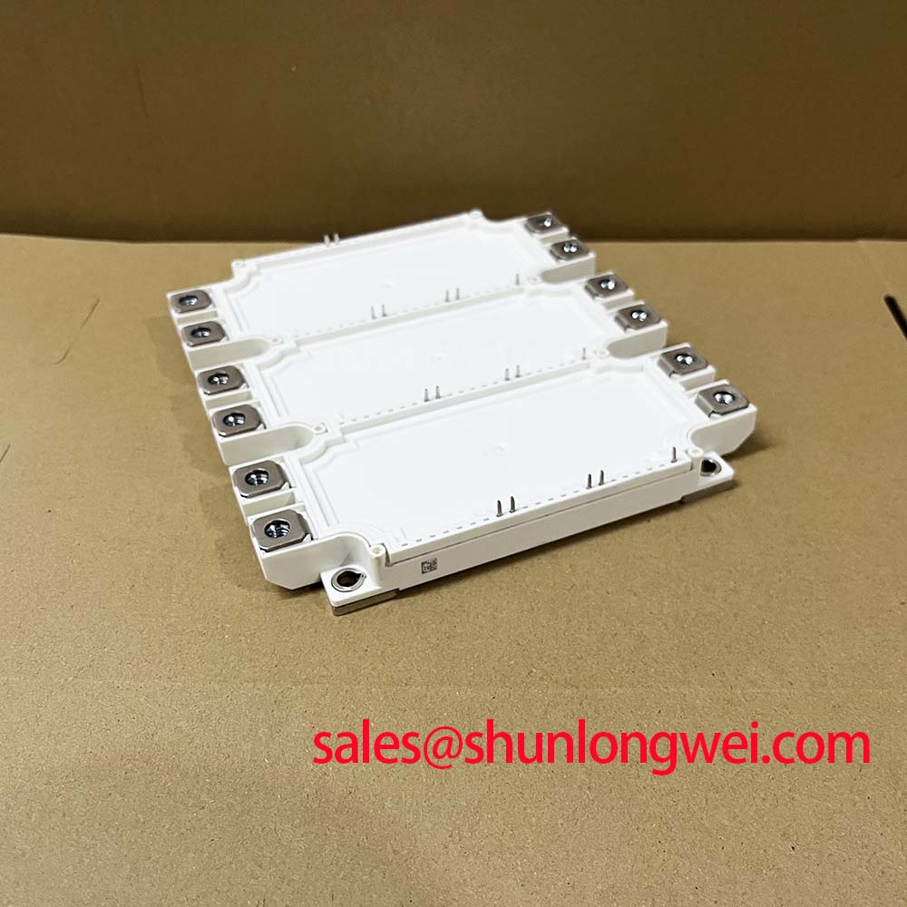
FS225R12KE3_S1 Infineon 1200V 225A Sixpack IGBT Module
The FS225R12KE3_S1 is a high-performance 1200V 225A IGBT module from Infineon, housed in the widely adopted EconoPACK™ 3 package. Utilizing TRENCHSTOP™ IGBT3 technology, this sixpack configuration integrates three inverter phases into a single footprint to maximize power density. For industrial systems prioritizing a compact 1200V inverter stage with integrated thermal monitoring, the FS225R12KE3_S1 is an optimal choice. It features a typical Vce(sat) of 1.70V and an integrated NTC thermistor, ensuring both high conduction efficiency and reliable temperature supervision. This module effectively addresses the challenge of thermal headroom in high-density motor control cabinets by minimizing both switching and conduction losses.
Application Scenarios & Value
Achieving System-Level Benefits in High-Efficiency Motor Control
Engineers often face the daunting task of increasing power output while simultaneously shrinking the physical dimensions of the power electronics assembly. The FS225R12KE3_S1 addresses this by providing a complete three-phase inverter bridge in one module. This configuration significantly reduces the complexity of DC-link busbar designs compared to using discrete components or multiple half-bridge modules. In Variable Frequency Drive (VFD) applications, the 225A continuous collector current rating at Tc=80°C allows for robust control of heavy industrial motors under varying load conditions. For systems requiring even higher current handling, such as those found in large-scale renewable energy converters, the FS450R12KE3 offers a higher power alternative within a similar technology family.
The integration of the NTC thermistor within the FS225R12KE3_S1 provides real-time thermal feedback directly from the substrate. This proximity allows for more aggressive Thermal Management strategies, as the system controller can react to temperature spikes with greater precision than external sensors allow. In high-precision Servo Drive environments, this translates to improved long-term reliability and protection against transient overloads. By utilizing the 1200V Vces rating, designers gain sufficient safety margins for 400V–480V AC line applications, effectively mitigating the risks associated with voltage transients in harsh industrial grids. The module's design naturally aligns with high-efficiency power systems that demand low parasitic inductance and high Switching Efficiency.
Technical & Design Deep Dive
Maximizing Switching Efficiency via Trenchstop IGBT3 Architecture
The core of the FS225R12KE3_S1 performance lies in the TRENCHSTOP™ IGBT3 chip architecture. Unlike older planar technologies, the trench structure allows for a higher cell density and better control over the charge carrier distribution. One can think of Vce(sat) as the internal resistance of a pressurized valve; by optimizing the trench geometry, Infineon has reduced the "friction" that electrons encounter, leading to the remarkably low 1.70V saturation voltage. This reduction in conduction loss is critical for maintaining high efficiency during steady-state operation.
Furthermore, the Fieldstop layer in the FS225R12KE3_S1 enables a thinner wafer design while maintaining the 1200V blocking capability. This thin-wafer technology is comparable to modern high-rise architecture where structural integrity is achieved through advanced materials rather than sheer bulk. The result is a significant reduction in Switching Loss (Eon and Eoff) and a softer turn-off characteristic. A softer turn-off reduces the dv/dt stress on the motor windings and lessens the requirements for EMI mitigation filters. When paired with high-performance gate drivers, the FS225R12KE3_S1 enables high-frequency PWM operation, which is essential for reducing the audible noise and torque ripple in high-end automation equipment. Detailed insights into these principles can be found in our guide on deconstructing IGBT hybrid structures.
Key Parameter Overview
Decoding the Specs for Enhanced Thermal Reliability
| Technical Specification | Value / Rating | Engineering Significance |
|---|---|---|
| Collector-Emitter Voltage (Vces) | 1200V | High safety margin for 400V/480V AC grids. |
| Continuous DC Collector Current (Ic) | 225A (at Tc=80°C) | Supports heavy-duty industrial motor loads. |
| Collector-Emitter Saturation Voltage | 1.70V (typical) | Minimizes heat dissipation during conduction. |
| Total Power Dissipation (Ptot) | 1050W (per IGBT) | Defines the limits for thermal design and cooling. |
| Temperature Sensor | Integrated NTC | Provides critical data for over-temperature protection. |
| Package Type | EconoPACK™ 3 | Compact sixpack layout for space-constrained designs. |
Download the FS225R12KE3_S1 datasheet for detailed specifications and performance curves from Infineon.
Frequently Asked Questions
- How does the integrated NTC thermistor in the FS225R12KE3_S1 simplify system design?
The NTC thermistor is mounted directly on the ceramic substrate inside the module. This provides an accurate representation of the baseplate temperature, allowing engineers to implement real-time Thermal Management without needing to mount external sensors on the heatsink, thus reducing assembly costs and improving response times. - What is the primary benefit of the IGBT3 Trenchstop technology used in this module?
The TRENCHSTOP™ IGBT3 technology offers a superior balance between conduction and switching losses. It enables a lower Vce(sat) while maintaining a robust Safe Operating Area (SOA), making it highly efficient for high-power-density applications. - Does the FS225R12KE3_S1 support paralleling for higher current applications?
While this module is a Sixpack configuration intended for standalone three-phase inverters, paralleling is possible with careful Gate Drive design and symmetric busbar layout to ensure balanced current sharing. However, for significantly higher current, modules like the FF450R12KE4 dual modules are often more practical. - How should the gate resistance (Rg) be selected for the FS225R12KE3_S1?
Selecting the optimal Gate Drive resistance involves a trade-off between switching speed and voltage overshoot. A lower Rg reduces switching losses but can increase EMI and voltage stress on the module. Engineers should refer to the switching loss curves in the datasheet for precise tuning. - What is the significance of the 1200V Vces rating in a 400V system?
In a 400V AC system, the DC link voltage is typically around 540V–600V. The 1200V rating provides a substantial buffer for the voltage spikes that occur during high-speed switching due to stray inductance, ensuring the device remains within its Safe Operating Area.
Strategic thermal planning and precise gate control are essential for maximizing the lifespan of power modules in industrial environments. By leveraging the low-loss characteristics of the FS225R12KE3_S1, designers can build more resilient and energy-efficient drive systems that meet the evolving requirements of modern automation.