
Content last revised on September 29, 2026
2MBI300N-060 Thermal-Electrical Optimization: Isolated DC-DC Power Supply Sizing for Practical Tuning
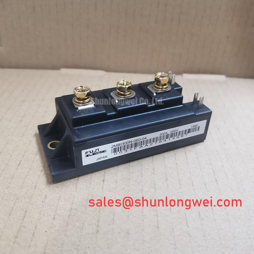
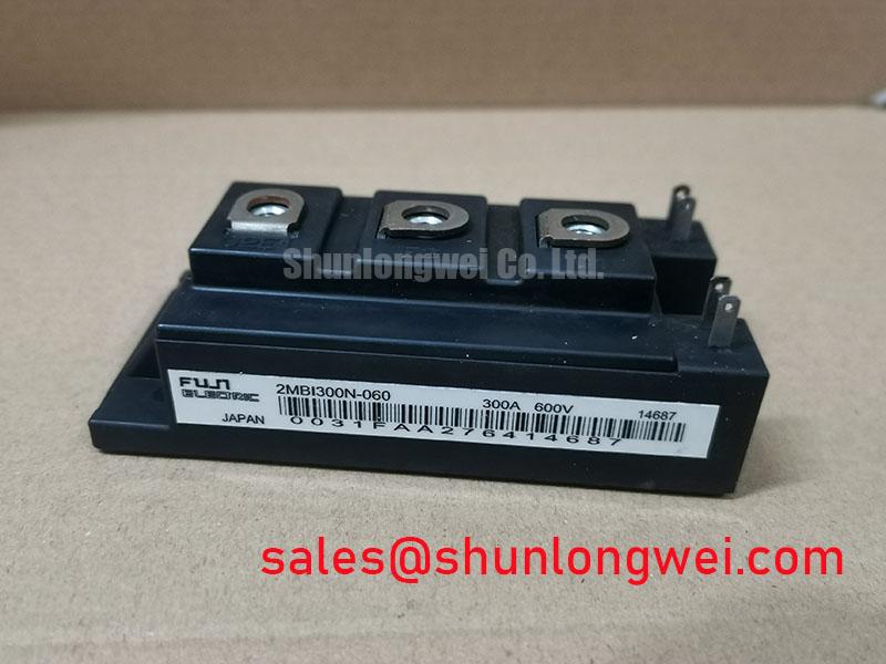
Before installing a 2MBI300N-060, verify the module marking and confirm that the equipment’s DC-link voltage and current requirements fall within its documented ratings. The stated product parameters identify a Fuji Electric IGBT module rated at 600 V and 300 A. These are product ratings, not a complete system operating envelope; switching conditions, cooling, protection, and the applicable manufacturer documentation must also be checked.
The available product data establishes the module category and its voltage and current ratings, but does not specify gate-drive supply requirements, reinforced-isolation voltage, common-mode transient immunity, or power-supply sequencing. Do not infer those values from the model number or from requirements used with another IGBT module. The system integrator should confirm the gate-terminal assignments and drive requirements using the applicable Fuji Electric documentation for this exact part and package.
Design Consideration: Select an isolated gate-drive supply only after checking its insulation rating, working-voltage conditions, and transient behavior against the complete converter’s electrical and safety requirements. Isolation claims for a supply do not establish the insulation capability of the assembled equipment. PCB spacing, barriers, connectors, and contamination conditions must be assessed at system level under the applicable standards.
For commissioning, inspect the driver supply rails and gate-emitter waveforms with suitable isolated measurement equipment. Check both turn-on and turn-off behavior under controlled conditions, then compare observed gate signals with the driver design and the module documentation. Unexpected pulses or waveform distortion warrant checking probe setup, return-path routing, driver-supply integrity, and common-mode coupling; they do not by themselves establish a module defect.
When evaluating the part for a commercial string inverter or micro-grid energy-storage converter, designers should verify compatibility with the switching topology, DC-link operating range, cooling arrangement, and fault response. Fuji Electric’s brake chopper IGBT module information provides product-family context, but it does not substitute for the 2MBI300N-060’s specific ratings or application documentation.
2MBI300N-060 Operational Boundaries: Evaluating Cosmic-Ray Robustness and Voltage Derating
A 600 V rating is an important selection boundary, not permission to operate a system at that voltage under every transient or switching condition. The available product data does not establish a cosmic-ray failure rate, single-event burnout limit, altitude derating curve, or FIT value for this module. Such figures should not be estimated from general IGBT behavior. For high-altitude installations or applications with demanding DC-link conditions, obtain applicable manufacturer guidance and assess the complete system’s operating and transient voltages.
Before reconnecting a replacement module, compare its terminal markings and physical layout with the equipment schematic and the exact module documentation. Confirm power-terminal and gate-terminal functions rather than relying on a similar-looking package. Inspect terminal surfaces, busbar alignment, insulating barriers, and clearances for contamination or mechanical interference. Required creepage and clearance distances depend on working voltage, insulation category, pollution conditions, and the equipment standard; they cannot be determined from the module’s 600 V rating alone.
Design Consideration: Keep the commutation path compact and minimize busbar loop inductance where practical. During turn-off, stray inductance interacting with current change can raise the voltage seen by the switching device. Validate peak voltage at the module terminals during representative switching tests, with measurement bandwidth and probe connections suitable for the edge rates involved. The resulting margin must be judged against the system limits and manufacturer data, not a generic derating percentage.
Mechanical retention also affects electrical connections. Check that busbars sit naturally on the terminals without imposing bending force, and use the equipment or manufacturer’s specified fastening procedure. The required torque is not established by the parameters provided here. For related topology evaluation, the 2MBI150UC-120 may be considered as a separate component in a system-level architecture; its presence does not imply electrical interchangeability or a prescribed pairing.
Cosmic-ray robustness and altitude behavior are system-specific qualification questions. Where they affect the application, request documented limits for the exact device and operating conditions, then validate DC-bus transients and protection response in the intended installation. Do not treat an unverified FIT estimate or an assumed voltage margin as a manufacturer specification.
2MBI300N-060 Circuit Protection and Reliability: Thermal Interface and Mounting Checks
At a stated current rating of 300 A, thermal performance depends on the complete path from the semiconductor module through its mounting interface and cooling system. The available data here does not provide junction-temperature limits, thermal resistance, baseplate flatness, thermal-interface material requirements, mounting torque, or switching safe-operating-area curves. Confirm each value in the applicable device documentation before setting assembly or protection limits.
During service, isolate the equipment according to its procedures, verify that stored DC-link energy has been discharged, and confirm the absence of hazardous voltage before handling the module. Remove old interface material without damaging the mating surfaces, then inspect the module base and heatsink for contamination, scratches, burrs, or uneven contact. Apply the interface material and tighten the fasteners using the sequence and torque specified for the exact assembly. A generic thickness or torque value should not replace those instructions.
Protection coordination must account for the module’s documented short-circuit capability and the system’s fault-clearing behavior. Select semiconductor fuses and protective devices using manufacturer curves and the equipment’s prospective fault conditions; a fuse’s current rating alone does not demonstrate adequate coordination. Review clearing time and energy let-through against the module documentation, and verify that the gate driver’s fault response and system disconnect operate as intended. No short-circuit withstand time or I²t limit is established by the ratings provided here.
For troubleshooting, compare temperatures and switching waveforms across operating conditions, and inspect for uneven heating, loose connections, or changes in cooling performance. These observations can guide investigation but are not standalone proof of a particular failure mechanism. Record the test conditions and compare results with a known-good baseline and the equipment limits. The IGBT design and integration resource covers broader integration considerations; exact assembly limits should still come from the relevant product and equipment documentation.
2MBI300N-060 Thermal-Electrical Optimization: Gate-Drive Loop Geometry
Trace the gate-drive loop from the driver output to the module gate and back through the documented emitter reference before powering the converter. Keep this loop compact, and route it to limit coupling with high-current switching paths. The exact terminal functions and any auxiliary emitter arrangement must be confirmed from the device pinout; do not assume a Kelvin emitter connection unless the applicable documentation identifies one.
Engineering Recommendation: Separate sensitive gate-drive return routing from high-current commutation paths where the documented terminal arrangement permits, then verify the result by observing gate-emitter voltage during switching. Shared impedance in the return path can introduce unwanted voltage into the gate signal, while parasitic inductance can contribute to ringing or overshoot. Layout changes should be evaluated with controlled switching tests rather than judged from routing appearance alone.
Check gate resistors, driver output stages, connectors, and solder joints against the circuit design and the module’s specified drive conditions. If oscillation or false turn-on is suspected, capture the gate-emitter waveform and relevant switch-node behavior using a measurement setup that minimizes probe-loop pickup. Review dead-time, interlock behavior, and fault shutdown as system functions; the product ratings alone do not define these settings.
Fuji Electric’s IGBT product information offers broader family context, but it does not establish that another series has the same pinout or drive requirements. The 2MBI300U4H-120-50 can be included in a replacement assessment, but suitability must be checked against the equipment schematic, mechanical interface, electrical ratings, and protection design; no direct interchangeability is asserted here.