Content last revised on September 10, 2026
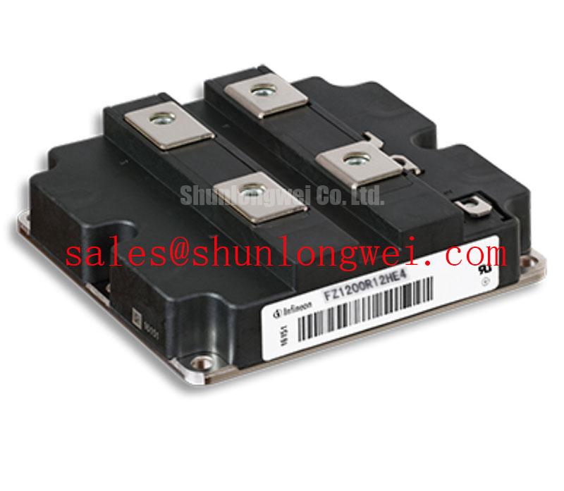
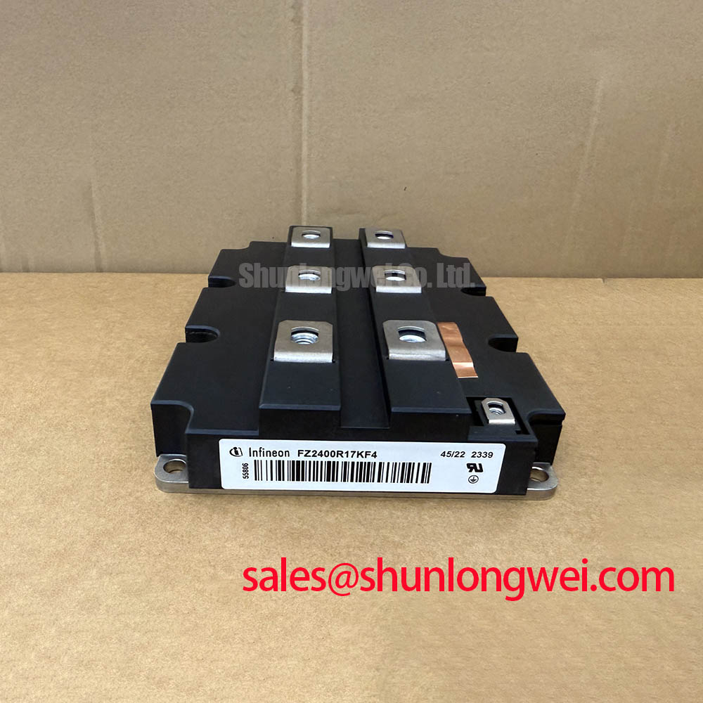
Infineon FZ1200R12KE3: High-Power Single IGBT Module for Industrial Systems
The FZ1200R12KE3 delivers optimized switching efficiency and robust current capability for high-power industrial converters. Rated at 1200V and 1200A, this module features a low thermal resistance of 0.022 K/W to support demanding application environments. Key benefits include minimizing conduction losses in heavy-duty converters and using a low stray inductance design to reduce transient voltage overshoot.
How does low VCE(sat) benefit large industrial converters? It reduces thermal strain by lowering on-state losses during continuous operation. What is the primary benefit of Trenchstop IGBT3? It provides low on-state saturation voltage to maximize system efficiency. For industrial motor drives prioritizing conduction efficiency, this 1200V module is the optimal choice.
Key Parameter Overview
Decoding Collector Current and Thermal Resistance for Optimized Power Density
| Parameter | Symbol | Value / Specification |
|---|---|---|
| Collector-Emitter Voltage | VCES | 1200 V |
| Nominal Collector Current | IC,nom | 1200 A (at TC = 80°C) |
| Maximum Collector Current | IC | 1700 A (at TC = 25°C) |
| Collector-Emitter Saturation Voltage | VCE(sat) | 1.70 V (typical, at Tvj = 25°C) / 2.00 V (typical, at Tvj = 125°C) |
| Total Power Dissipation | Ptot | 5.6 kW (at TC = 25°C) |
| Thermal Resistance, Junction to Case | Rth(j-c) | 0.022 K/W (per Transistor, DC) |
| Diode Forward Voltage | VF | 1.80 V (typical, at Tvj = 25°C) / 2.00 V (typical, at Tvj = 125°C) |
| Input Capacitance | Cies | 86 nF |
| Stray Inductance | LsCE | 12 nH |
| Package Housing | Footprint | IHM-A (130mm x 140mm) |
| Module Weight | W | 1500 g |
Download the FZ1200R12KE3 datasheet for detailed specifications and performance curves.
Application Scenarios & Value
Reducing Switching Losses in Multi-Megawatt Industrial Inverters
Industrial power electronics demand modules that sustain continuous loads while handling grid-level transients. The FZ1200R12KE3 is designed for high-current applications such as megawatt-class wind turbines, large solar inverters, and heavy-duty uninterruptible power supplies. In a typical wind turbine application, a sudden grid dip triggers a low-voltage ride-through scenario. During this phase, the generator converter undergoes severe current spikes. The module's peak collector current tolerance of 2400A allows the system to ride through these transients without triggering overcurrent shutdown.
Similarly, in medium-voltage industrial drives operating large conveyors or pumps, motor startup generates high inrush currents. The low on-state saturation voltage of 1.70 V minimizes conduction heating, helping system designers meet stringent thermal margins. This efficiency also extends to regenerative braking systems in heavy machinery, where energy is fed back into the grid, requiring efficient high-power conversion.
For applications requiring higher switching frequency optimization rather than standard Trenchstop IGBT3, the related FZ1200R12KF5 offers a fast-switching alternative, whereas systems with lower current demands can utilize the FZ900R12KE4 rated at 900A. Refer to our guide to IGBT selection to balance current density and thermal load.
Technical & Design Deep Dive
A Closer Look at the Low Stray Inductance and Trenchstop IGBT3 Technology
The FZ1200R12KE3 utilizes Infineon's Trenchstop IGBT3 chip technology. This generation is widely used in standard high-power modules because it balances robust gate controllability and low losses. Designers can also calculate VCE(sat) variation across different temperatures using established manufacturer application notes. Understanding the fundamentals of IGBT module operation is critical for selecting the right switching topology.
To understand saturation voltage, think of VCE(sat) as a narrow toll booth on a busy highway. The wider the toll booth (lower saturation voltage), the faster and smoother the cars (current) flow without bottlenecks (heat buildup). In this module, a typical VCE(sat) of 1.70 V represents an exceptionally wide toll booth for a 1200A current, drastically reducing conduction power losses during continuous operation.
Similarly, the internal thermal resistance of 0.022 K/W acts as a high-speed thermal expressway. Just as a wider river channel allows water to drain quickly to prevent flooding, this low resistance allows heat generated inside the silicon junction to drain rapidly to the heatsink. Proper design strategies for minimizing thermal resistance are covered in our guide on unlocking IGBT thermal performance.
Furthermore, the low stray inductance of 12 nH within the IHM-A package minimizes the voltage spike (V = L * di/dt) during high-speed switching off. This reduces the electrical stress on the gate drive and permits simpler snubber circuits.
Frequently Asked Questions
Addressing Critical Integration and Operation Engineering Challenges
What voltage margin is recommended when implementing the FZ1200R12KE3 in 690V grid systems?
Although the module has a maximum blocking voltage rating of 1200V, industrial design guidelines recommend maintaining a 20-30% buffer to protect against inductive switching voltage spikes. For a 690V AC system where the nominal DC-link voltage typically rests around 975V, utilizing a 1200V IGBT module requires precise active clamping or snubber circuits to prevent transient overvoltage breakdown during hard turn-off.
How does the thermal resistance of 0.022 K/W directly affect heatsink selection and overall power density?
A low thermal resistance of 0.022 K/W means the temperature delta between the internal silicon junction and the copper case is kept minimal even at full load. This allows engineers to use smaller aluminum or liquid-cooled heatsinks, thereby increasing system power density while maintaining the operational junction temperature well below the maximum limit of 125°C.
Why is a negative gate-emitter voltage recommended during the off-state of the FZ1200R12KE3?
Due to the high nominal collector current of 1200A, fast switching transients produce significant voltage fluctuations (dv/dt) across the parasitic Miller capacitance. Applying a negative off-state gate voltage (typically -15V) ensures the gate remains firmly discharged, preventing accidental turn-on (parasitic turn-on) that could lead to catastrophic shoot-through.
As industrial networks shift toward higher electrification and carbon neutrality goals, power density and conversion efficiency will remain the primary drivers of system design. Optimizing high-power conversion setups with components that limit switching losses ensures that future grid systems and heavy industrial drives remain compliant with evolving energy efficiency directives.