Content last revised on October 14, 2026
FZ2400R17KF6C_B2 Operational Boundaries: Preventing Ceramic Substrate Rupture During Installation
Model: FZ2400R17KF6C_B2 | Manufacturer: Infineon | Official Specification: 1700 V rated voltage, 2400 A rated current | Package: Module | Device class: IGBT Module
I check the heatsink contact surface and mounting seats before bringing the FZ2400R17KF6C_B2 into position, with the equipment isolated and the DC link verified discharged. As a Design Consideration, a replacement module should sit on the prepared interface without bolts pulling it into alignment. Residual thermal compound, raised burrs around mounting holes, or distorted mounting hardware can concentrate mechanical loading before the electrical connections are installed.
Inspect the baseplate contact profile against the approved mechanical drawing rather than assuming that every departure from flatness is damage. Evaluate heatsink flatness separately using suitable dimensional inspection equipment. Do not grind, bend, or otherwise reshape the module to match an uneven mounting surface. The practical objective is a supported thermal interface without forcing the package to accommodate an installation defect.
For thermal interface material, follow the approved compound specification and application method. Uniform coverage matters, but an arbitrary coating thickness is not a substitute for the assembly instructions. Check that dispensing, spreading, and seating do not leave contaminated patches or excessive accumulation around mounting features. A thermal contact problem can resemble inadequate cooling elsewhere, so inspect the mating surfaces before attributing an elevated operating temperature to the semiconductor itself.
Use a calibrated torque tool and the manufacturer’s specified tightening sequence and torque. Where the assembly instructions call for staged diagonal tightening, bring the fasteners down progressively rather than fully loading one corner first. Field Alert: Never use mounting bolts to pull a misaligned module against the heatsink; correct the seating problem before applying the specified torque.
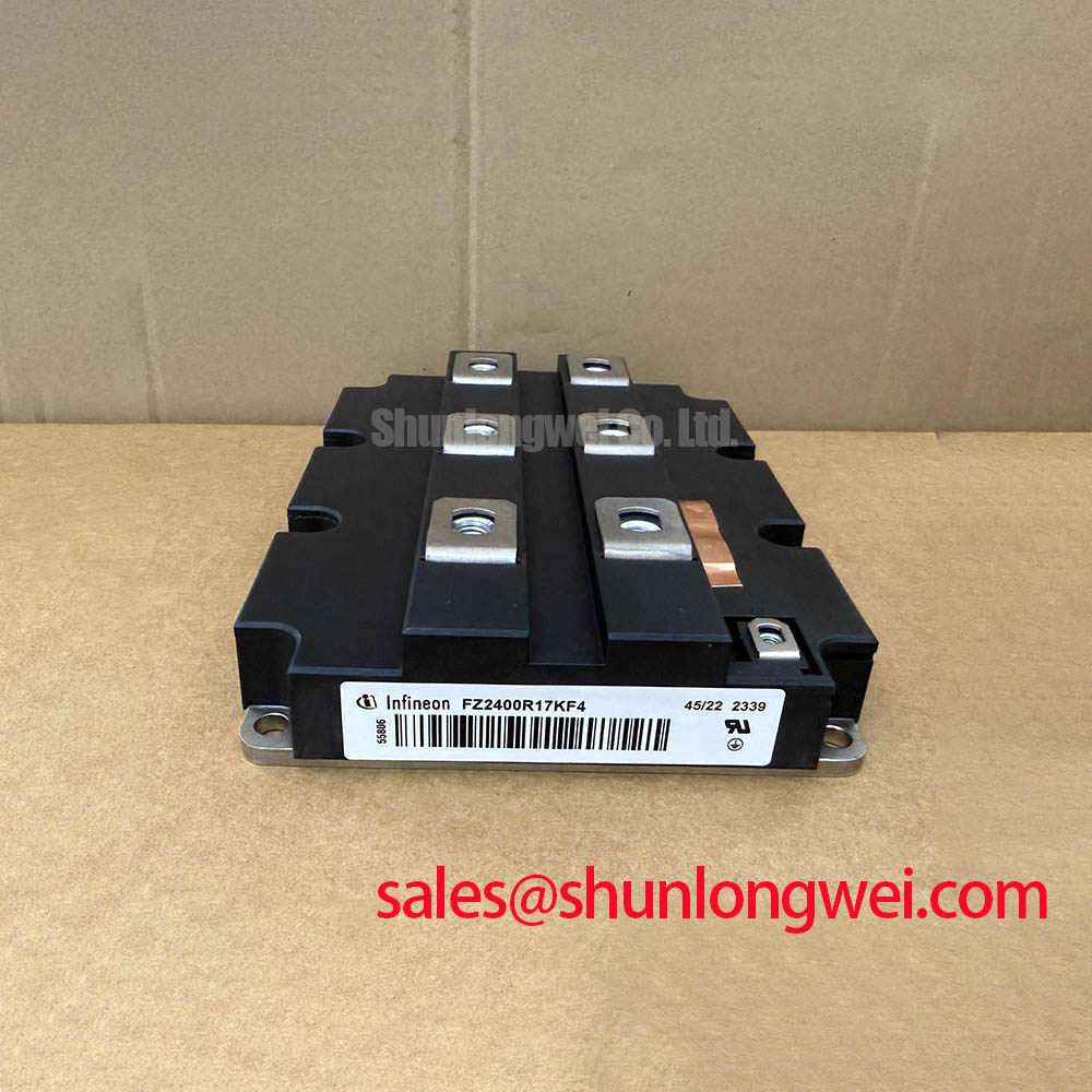
For replacement assessment, compare the mechanical drawing, terminal arrangement, and cooling interface with the existing assembly. The related FZ2400R17KF4 provides another model to examine during a specification comparison, not an automatic interchangeable replacement. Matching headline electrical ratings does not establish matching mounting geometry or thermal behavior.
FZ2400R17KF6C_B2 Operational Boundaries: Oscilloscope Waveform Verification and Switching-Transient Control
Measure the gate waveform at the module connection rather than relying exclusively on the legacy driver board’s test point. As a Design Consideration, the interconnection between driver and module contributes impedance, so a clean board trace can coexist with ringing at the device terminals. Use appropriately rated differential or isolated measurement equipment and keep the measurement loop compact enough to avoid confusing probe pickup with actual switching behavior.
When evaluating external turn-on and turn-off gate resistors, identify whether the installed driver provides separate charging and discharging paths. Check its sourcing and sinking capability against the gate-charge requirements and switching conditions of the intended device. Resistance changes affect transition speed, switching energy, voltage overshoot, and susceptibility to unwanted turn-on; selection therefore belongs to the complete driver and power-stage assessment rather than a fixed resistor prescription.
A controlled commissioning sequence should capture gate voltage and collector-emitter voltage together, with current measurement where the test arrangement permits. Compare the waveforms under documented operating conditions before changing the gate network. Excessive ringing warrants inspection of the gate return path, power-loop geometry, and measurement setup alongside resistor selection. Simply slowing every transition can exchange an overshoot problem for additional dissipation.
If the existing driver uses negative off-state bias, assess that bias against the device’s permitted gate-voltage limits and the measured transient excursion. Keep the gate return referenced to the designated module terminal, and evaluate isolation and signal routing where common-mode disturbances enter the control circuit. The Infineon TRENCHSTOP™ IGBT3 application note offers switching-design context for its stated device family; its settings are not specifications for this module.
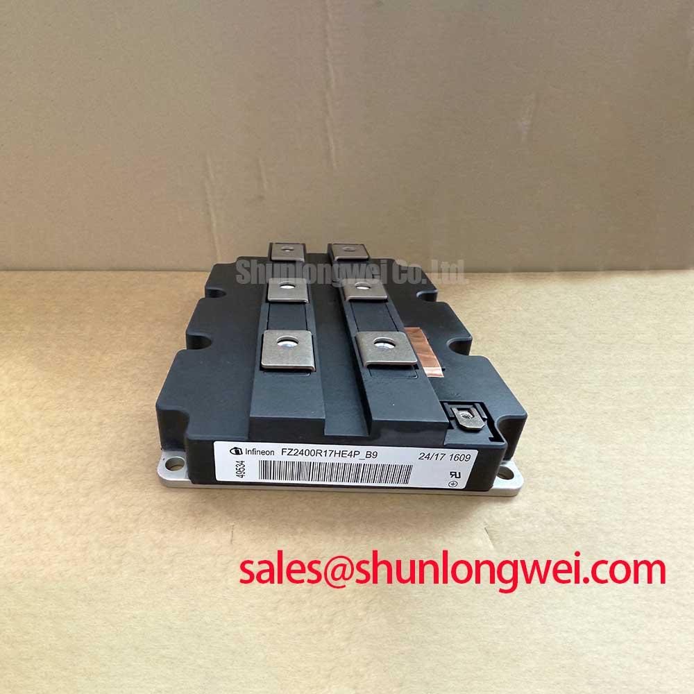
The FZ2400R17HP4_B29 can also enter a broader power-stage comparison, but its driver requirements and terminal implementation need independent evaluation. Neither its designation nor its position in a related product range establishes that an existing gate board can operate it unchanged.
Field Diagnostics & Commissioning: DC-Bus Operating Voltage Headroom Derating in FZ2400R17KF6C_B2 Topologies
Capture the highest collector-emitter voltage during the operating events that stress the installed topology, including switching transitions and DC-link excursions. The 1700 V rating is an Official Specification; selecting a working bus voltage requires the system designer to account for the actual voltage imposed across each device. Use the circuit diagram to establish that stress rather than assigning the entire bus voltage to every switch without examining the topology.
As a Design Consideration, engineers evaluating a utility-scale 1500 V central solar photovoltaic inverter should distinguish the system’s DC voltage designation from the blocking voltage across an individual module. Review maximum input conditions, bus regulation, switching overshoot, and protective shutdown behavior. This is a compatibility assessment, not a claim that the FZ2400R17KF6C_B2 is approved for that equipment.
Where regenerative energy can reach the DC link, examine the existing energy-management path. If the equipment includes a braking chopper and resistor, verify their control response, thermal protection, connections, and duty limits against the equipment documentation. A functioning switching stage cannot compensate for an unavailable energy sink. Equally, a bus excursion does not by itself identify a failed chopper: control commands, incoming energy, sensing, and connections require separate checks.
For elevated-altitude installations, treat atmospheric-neutron-induced single-event burnout as a manufacturer-supported reliability assessment, not a calculation derived from voltage rating alone. Request applicable device-specific data relating blocking voltage, temperature, and environmental conditions to the required reliability target. Any resulting FIT estimate needs its stated source, model assumptions, and operating profile. No universal altitude threshold or percentage derating is assigned here.
The Unlocking Efficiency in Industrial Drives article provides broader switching and thermal-design background, but does not identify this module as IGBT7. For manufacturer product-family information, consult the Infineon IGBT Modules & Discretes Official Portfolio. Keep technology-family guidance separate from the device-specific evidence used to approve operating stress.
Assembly Integrity & Layout Architecture: Implementing Terminal Screw Engagement Depth for FZ2400R17KF6C_B2
Check the complete terminal hardware stack before selecting screw length: conductor thickness, washers, terminal seating, and available thread depth all affect engagement. As a Design Consideration, a screw can reach the bottom of a threaded connection before producing the intended clamp load. Conversely, inadequate engagement can leave an apparently tightened connection mechanically unsuitable. Use the approved terminal drawing and assembly instructions to establish the acceptable hardware combination.
Support the busbar so that it meets the terminal naturally, without sideways force or a gap that tightening must close. Inspect conductor contact faces for contamination, damage, and uneven seating. Apply the specified terminal torque using the prescribed washer arrangement; a different washer stack can change both engagement and clamping behavior. Avoid transferring cable weight or rigid busbar misalignment into the module terminals.
For vibration and thermal cycling, assess external supports and conductor movement without assuming an undocumented internal construction. The installation should accommodate the equipment’s expected movement while maintaining secure contacts. Follow the equipment maintenance procedure for connection checks rather than repeatedly retightening terminals by habit. Local discoloration or abnormal heating warrants inspection of the joint, conductor condition, loading, and cooling together.
Preserve the designed creepage and clearance paths around power terminals, mounting hardware, and nearby grounded structures. Assess these distances using the applicable equipment standard and installation conditions, including pollution degree and altitude where relevant. Added washers, replacement busbars, loose strands, or displaced insulating barriers can alter the original arrangement even when the module itself fits.
Before re-energization, confirm terminal identification against the circuit drawing and inspect gate wiring for pinching beneath covers or busbars. With external circuits appropriately disconnected, cold-state resistance and diode-mode comparisons can help identify gross abnormalities, but they do not establish full-voltage switching health. Record the assembly checks, then follow the equipment’s controlled commissioning procedure while observing connection temperatures and electrical behavior under authorized test conditions.