

Content last revised on September 26, 2026
Preventing Spurious Faults: Negative Gate Bias and Miller Clamp Assessment for FZ3600R17KE3
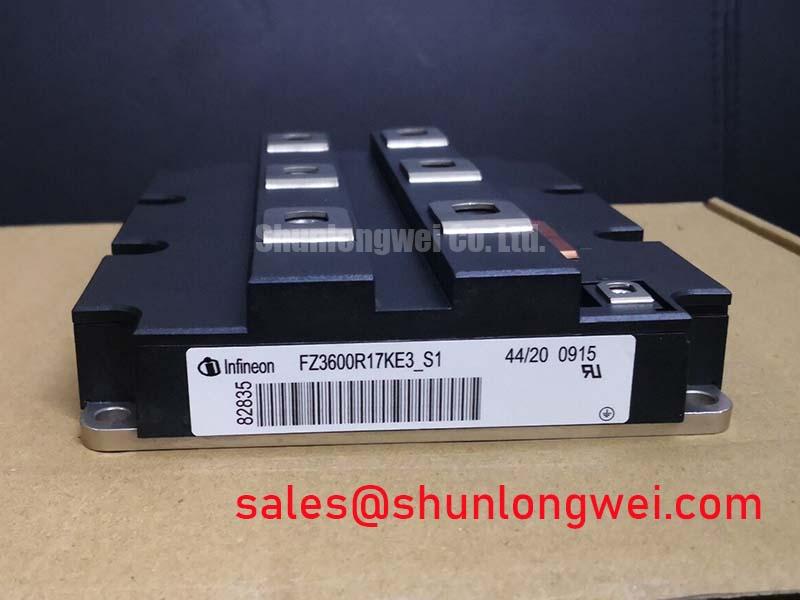
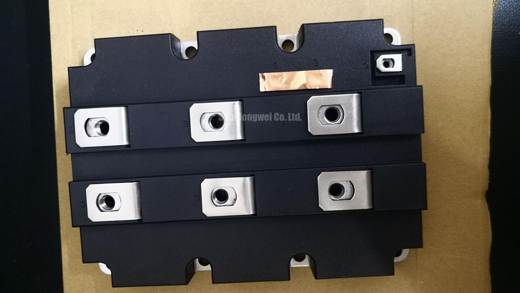
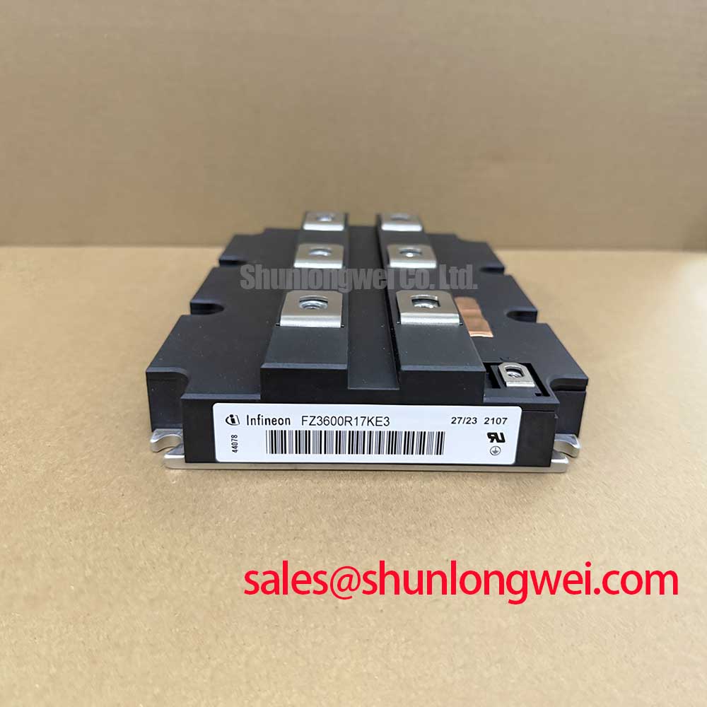
With the equipment isolated and the DC link verified discharged, compare the removed module’s terminal layout with the FZ3600R17KE3 before checking its cold terminal resistance against a known-good unit. The Infineon IGBT module is rated 1700 V and 3600 A (Official Specification). Those ratings establish a starting point for identification, not a complete replacement decision: the circuit topology, mounting interface, gate connections and operating margins must also match.
When a companion switch changes state, voltage movement at the collector can couple into the gate circuit of a device that should remain off. A shutdown that appears intermittent may therefore warrant a gate waveform check before the module is condemned. Probe the gate relative to its intended emitter reference during switching, then compare the trace with the original drive design and, where available, a known-good phase. A multimeter cannot show a brief gate excursion.
Design Consideration: Negative off-state gate bias and an active Miller clamp are two drive-circuit methods for resisting unwanted turn-on. Neither should be assigned a voltage or assumed to be present simply because the power module carries a 1700 V rating. Check the installed driver schematic, its off-state supply, clamp connection and fault records. If the gate trace moves toward turn-on during a companion switch transition, examine the driver return path and clamp operation alongside the module; the waveform alone does not identify a failed part. The discussion in Evolution of Negative Off-Bias Gate Drive Circuits provides context for evaluating the drive approach without treating a generic bias value as this module’s specification.
Keep the gate-drive loop compact and away from the main current path where the equipment layout permits. This is a Design Consideration intended to reduce coupling during fast switching; final trace spacing, clearance and off-state bias are system-level decisions to validate under the inverter’s actual voltage and switching conditions. For an equipment identification check, the FZ3600R17KE3 product reference can be compared with the removed unit, but the original module documentation and equipment drawings remain necessary for terminal and drive verification.
Assembly Integrity and Isolated Driver Supply Integration
Before connecting the replacement module, inspect the mounting surface, terminal contact faces and busbar alignment. A terminal that draws a busbar into place as it is tightened may indicate a mechanical mismatch rather than an acceptable fit. Check that the installed driver supply and its isolation arrangement correspond to the original equipment design. The module’s voltage rating does not specify the driver supply’s isolation rating or its common-mode transient immunity; those belong to the driver and system documentation.
Field Alert: Do not tighten a misaligned busbar against the module terminals; correct the mechanical fit before applying the equipment manufacturer’s fastening procedure.
For a drive circuit under investigation, measure its supply at the driver during the operating states that preceded the fault. Supply disturbance, an unexpected shutdown command or a gate waveform anomaly may point to different parts of the same circuit. Engineering Recommendation: Assess isolation and transient immunity against the installed driver’s specifications, with measurements referenced to the correct local return. Do not infer a required isolation voltage or immunity threshold from the FZ3600R17KE3 part number.
The DC-link connection deserves a separate inspection. Loose joints, a displaced snubber capacitor or an altered busbar route can change switching transients even when the module itself passes a cold check. Minimize the power-loop path where practical to limit inductive overshoot, then verify the collector-emitter switching peak against the equipment’s DC-link conditions and the module’s 1700 V rating. The acceptable physical layout is determined by the complete assembly and test results, not by an assumed inductance target for this module.
In a utility-scale central solar inverter, including a system described as a 1500 V installation, identify the voltage applied to each switch position rather than equating the installation label with the stress on one module. A 1700 V device rating alone does not establish adequate switching margin in that circuit. Infineon’s official IGBT portfolio is a manufacturer reference for the device category; position-specific limits still require the applicable module data and inverter design records.
Emitter Return Routing and Replacement Compatibility
Trace the gate-driver return from the driver board to the module terminal identified in the original connection drawing. Do not assume that a visually similar small terminal is an auxiliary emitter connection: confirm its function before attaching a probe or transferring a harness. Where a separate emitter-sense return is specified, routing it independently of the main load-current path is a Design Consideration for reducing the influence of power-path voltage movement on the measured gate voltage.
If a repaired phase shows gate ringing or uneven switching, compare its gate and return connections with an unaffected phase before changing drive components. Inspect connector seating, terminal tightness and evidence of heat at the power joints. Then capture waveforms using a measurement setup appropriate to the equipment voltage and compare them under equivalent operating conditions. Ringing can involve the driver, its return path, the power layout or the measurement connection; it should not be assigned to the module from one trace.
The 3600 A current rating (Official Specification) is likewise not a substitute for a thermal review. For pulsed loading, use the applicable manufacturer transient thermal impedance data, if available for the exact device version, to evaluate peak junction temperature under the equipment’s measured loss profile. Without that data and the cooling-system conditions, a cold resistance check cannot establish thermal suitability or service life. Inspect the cooling interface for flatness, contamination and proper assembly using the equipment manufacturer’s procedure.
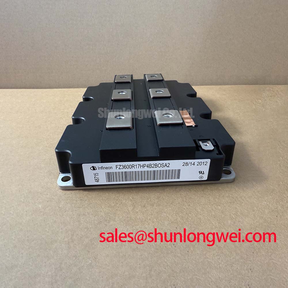
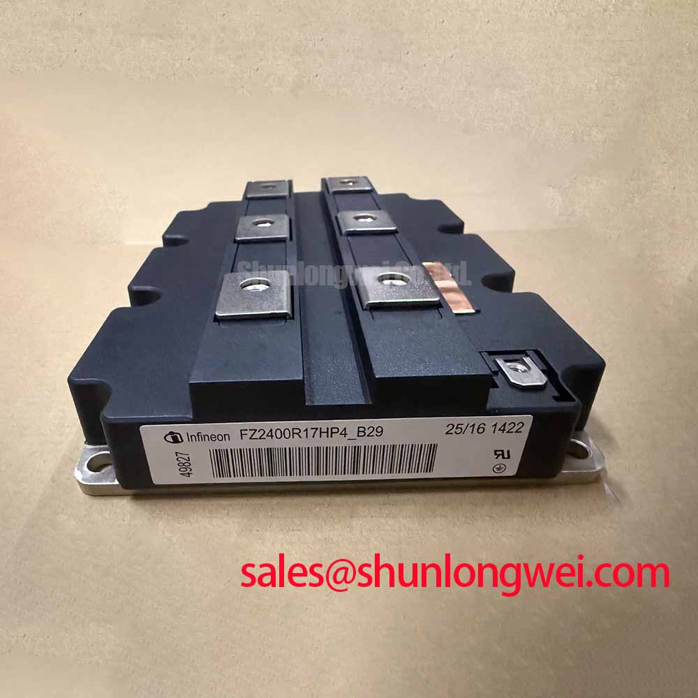
When comparing service candidates, FZ3600R12HP4 is a separate model reference, not an automatic substitute for FZ3600R17KE3. Verify voltage and current ratings, terminal mapping, package dimensions, cooling interface and gate-drive requirements for each exact part before considering a change. A matching current figure or similar-looking housing cannot establish electrical or mechanical interchangeability.
Desaturation Detection and Controlled Fault Turn-Off
If the inverter reports a desaturation fault, record the operating state and the sequence of driver indications before resetting it. Desaturation monitoring observes collector-emitter behavior while the switch is commanded on; a fault report may reflect an overcurrent event, a gate-drive problem, sensing-circuit behavior or the protection circuit’s timing. Review the installed driver schematic and compare fault captures with a healthy phase where the equipment permits safe testing.
Design Consideration: Short-circuit detection and controlled turn-off should be evaluated as one system function. Detection must respond within the limits established by the exact module documentation and driver design, while turn-off must control the resulting voltage rise at the actual DC-link voltage and power-loop inductance. Do not assign a universal short-circuit withstand time or soft turn-off profile to FZ3600R17KE3 without an applicable official specification.
After a fault, verify the module’s cold terminal behavior against the service procedure, inspect the gate connection and check the driver’s desaturation sensing path before energizing the phase again. If testing proceeds, capture the collector-emitter and gate waveforms with equipment rated for the installation and confirm that switching peaks remain within documented limits. The decision to return the inverter to service depends on those circuit measurements, the protection records and the exact replacement documentation—not on the module’s headline ratings alone.