

Content last revised on October 26, 2026
Industrial Bezel Mechanical Envelope Tolerances & Mounting Screw Torque Optimization
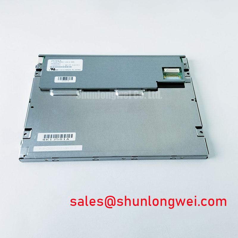
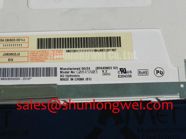
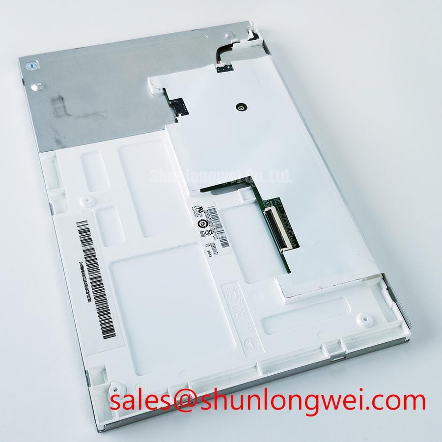
Inspect the bezel clearance and gasket contact around the AUO G085VW01 V0 before tightening the display into its enclosure; uneven frame loading can change screen uniformity and complicate fault diagnosis. Photograph the original cable routing, mounting points, and connector orientation before removal so the replacement assessment includes the complete display assembly rather than the panel label alone.
The G085VW01 V0 is an industrial LCD/HMI panel with a TFT-LCD active-matrix color display module construction. For maintenance planning, distinguish the panel from the surrounding controller, protective window, touch assembly, and backlight power circuitry. Those interfaces determine whether an otherwise matching display can operate correctly in the existing equipment.
Check that the mounting frame supports the intended attachment points without forcing the display perimeter against an uneven bezel. As a Design Consideration, inspect gasket seating, bracket flatness, and clearance around the cable exit before applying final fastening load. A folded seal or trapped cable can introduce local pressure even when the visible bezel appears correctly aligned.
For the G085VW01 V0 installation, mounting dimensions, screw engagement, and tightening limits belong to the panel drawing and enclosure assembly specification. Do not transfer a torque setting from another display merely because the fasteners look similar. Where the bracket arrangement permits, progressively tightening opposing attachment points can help distribute load; the completed assembly should then be checked for distortion and optical changes.
Compare a dark image and a uniform gray image before and after securing the assembly. Changes that follow fastening adjustments may indicate mounting stress, but illumination uniformity, image settings, and viewing position must remain consistent during the comparison. Avoid pressing the active surface to reproduce a defect: this introduces another mechanical variable rather than isolating the original one.
For potential integration into a factory automation machine-tool HMI operator terminal, assess bezel fit alongside connector access and service clearance. Route the flexible cable without creasing it or allowing the enclosure edge to become its bending point. Provide system-level strain relief so vibration and maintenance movement do not repeatedly load the connector or cable termination.
Maintenance Note: Periodically inspect ventilation paths and perimeter gaskets so dust accumulation or displaced sealing material does not compromise cooling or create uneven bezel pressure.
Polarizer Durability & Optical Surface Inspection under Direct Industrial Lighting
Examine the unpowered screen under diffuse and oblique lighting before assessing powered image quality. Surface contamination, scratches, and marks on a separate protective window can resemble defects within the display. As a Design Consideration, identify which optical surface carries the mark before cleaning, and use the cleaning method approved for that surface rather than assuming the window and panel tolerate the same treatment.
The distinction between surface reflection and image contrast matters under strong overhead lighting. An anti-glare treatment, where specified, does not by itself establish sunlight readability. Evaluate displayed text and gray levels through the actual enclosure window at the intended operator position. The general optical role of polarizers is described in Liquid-Crystal Display (LCD) Polarizers and Optical Glass; it does not establish a coating specification for this model.
For replacement screening, keep the exact G085VW01 V0 revision separate from visually similar panels. The following comparison identifies the evidence needed before treating another panel as compatible; it does not nominate an interchangeable model.
| Assessment item | G085VW01 V0 baseline | Alternative panel assessment |
|---|---|---|
| Manufacturer and identity | AUO G085VW01 V0 | Record complete manufacturer, model, and revision |
| Display construction | TFT-LCD active-matrix color display module | Match electrical and optical requirements, not category alone |
| Dimensions, interface, supply, and timing | Consult Datasheet | Compare connector assignment, drawing, and timing requirements |
| Viewing behavior and surface treatment | Assess against revision-specific optical specifications | Check orientation, gray-level visibility, and reflections in the enclosure |
| Mounting compatibility | Match the original assembly drawing | Verify attachment points, cable exit, and bezel clearance |
Do not assign TN, IPS, or MVA viewing characteristics to this model without its optical specification. As a Design Consideration, compare gray-level visibility from the intended operating positions rather than relying on a technology label. The TFT LCD technology reference explains the broader technology distinctions without establishing model-specific viewing angles.
Flashlight Dark-Shadow Optical Diagnostic to Isolate Logic vs. Backlight Failure Modes
Illuminate a dark powered screen obliquely with a flashlight while the controller displays a known test image. A faint recognizable image supports further investigation of the illumination path, but it does not independently identify a failed backlight or driver. No visible image is also inconclusive because signal, timing, panel power, and image contrast affect the observation.
As an Engineering Recommendation, display red, green, and blue test fields in sequence, followed by gray and dark fields. Record whether an anomaly stays at the same screen location, changes with image content, or appears only during transitions. Compare with a known-good signal source where practical, keeping controller settings unchanged.
Persistent lines should prompt inspection of the accessible signal connector, cable seating, and controller output before assigning an internal panel fault. Disconnect power before reseating connections, and check that each locking mechanism fully engages without pulling the flexible cable sideways. A line defect alone does not establish an internal bond fracture.
Separate backlight brightness degradation from intermittent shutdown by recording behavior after startup and thermal stabilization under repeatable settings. Brightness maintenance and mean time between failures describe different properties; neither should be converted into a service-life claim without manufacturer test conditions. For broader troubleshooting context, The Ultimate Guide to Industrial TFT LCD Technology provides supporting background for separating optical, electrical, and assembly-related observations.
Assessing Frame Lag & Image Smearing in Cold Storage & Outdoor Industrial Facilities
Compare moving edges and changing text after temperature stabilization before attributing visible trailing to a communication fault. As a Design Consideration, lower temperature can slow liquid-crystal transitions, while controller buffering and source timing can create separate delays. Observe a static pattern alongside moving content to distinguish persistent image defects from transition-dependent behavior.
For any cold-start assessment of the G085VW01 V0, the test envelope must remain within its documented operating conditions. Evaluate storage exposure separately from powered operation; a storage qualification does not establish acceptable cold-start image response. Any timing compensation should be validated at system level rather than introduced through arbitrary controller adjustments.
During enclosure temperature changes, inspect for condensation and differential movement between the frame, window, and panel supports. Allow moisture to dissipate before energizing an affected assembly. Keep seals seated without adding pressure to the optical stack, and inspect cable routing for movement caused by bracket expansion or contraction.
After the assembly returns to a stable temperature, repeat the same image sequence and inspect connector retention, gasket seating, and mounting-related uniformity. Record the test conditions and observed recovery so subsequent maintenance can distinguish repeatable temperature behavior from a developing cable, controller, or illumination fault.