Content last revised on October 10, 2026
G104STN01-6 Display Identification and Replacement Checks
- Record the display model and manufacturer marking before removing the existing panel.
- Inspect the bezel opening, perimeter gasket, mounting points, and cable locking hardware for compression or movement.
- Check the panel supply and backlight interface against the original system documentation before applying power.
- Compare the replacement image path with a known good controller output before changing the display assembly.
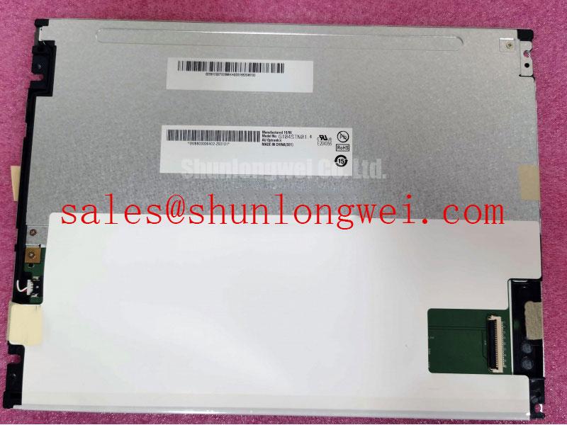
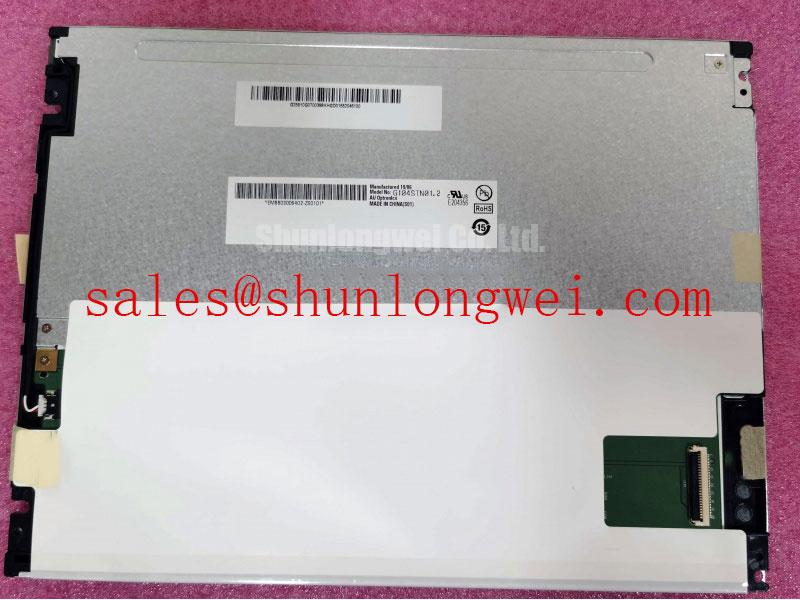
G104STN01-6 is an AUO TFT LCD active matrix color display module used in industrial display and HMI applications. Field replacement work should begin with mechanical envelope, interface compatibility, and backlight architecture rather than visual size alone.
| Model | G104STN01-6 |
| Manufacturer | AUO |
| Product category | LCD Display Module |
| Display construction | TFT-LCD Active Matrix Color Display Module |
Flush-Mount Open-Frame Bezel Integration and Perimeter Gasket Shock Isolation
Start mechanical installation by checking that the chassis opening supports the panel perimeter without forcing the bezel into the active viewing area. A gasket should distribute enclosure contact around the frame; isolated pressure points can create optical non-uniformity, dark regions, or mechanical stress that changes as the cabinet temperature moves.
A model-specific mechanical drawing is needed to establish the outer dimensions and mounting tolerances. For a field replacement, measure the original cut-out, mounting-hole pattern, connector clearance, and rear cable bend path. Designers should preserve clearance around the active area and allow the enclosure to absorb vibration without transferring concentrated load into the display frame.
As a general design consideration, a cross-pattern fastening sequence may use a light, even tightening approach, with the fastener size and final torque controlled by the enclosure and panel drawing rather than treated as a generic AUO specification. Tighten progressively across opposite points while checking for bezel distortion and changes in the displayed grey field.
High-speed display links should be routed away from switching power sections and motor-drive conductors. Where the system uses differential signalling, a controlled differential impedance target such as 100 Ω ±10% may be used as a design consideration when supported by the interface requirements, with pair skew controlled by the host board and cable construction. Validate the result with the complete cable assembly, not only the bare controller board.
Industrial EMI Noise Immunity, Chassis Shielding Continuity and Common-Mode Ferrite Chokes
Pixel jitter and horizontal noise bands near variable-frequency drives often require a complete cable and enclosure review. Confirm that the display cable shield has a short, low-inductance chassis connection at the intended entry point, and check that painted surfaces, loose covers, or anodized contact areas have not interrupted the shielding path.
A 360-degree shield termination is a design consideration for high-noise cabinets when it is compatible with the connector and enclosure construction. A pigtail connection may introduce additional coupling into the signal path. Common-mode ferrite components can also be evaluated when conducted interference remains after grounding and routing have been corrected, but their impedance behaviour must be checked across the actual noise spectrum.
The display should be tested while the cabinet operates in its normal switching state. Compare the image with the drive disabled and enabled, then observe whether the disturbance follows cable position, chassis bonding, or a particular motor-drive operating point. This separates a display-link susceptibility issue from a supply ripple or controller timing problem without assigning a single cause to the visible symptom.
For systems using PWM backlight control, the integrator should verify the driver’s permitted switching frequency, duty-cycle response, and enable polarity. Audible noise, rolling bands, or visible flicker should be checked at several brightness settings rather than judged at full illumination only. AUO’s industrial display and embedded systems resources provide useful background when comparing interface and enclosure requirements.
Display Data Mapping Alignment and Signal Integrity
Split-screen images, incorrect colour order, or unstable text edges should prompt a mapping and timing review before replacing the panel. Confirm the host controller’s pixel mapping, channel order, bit assignment, and polarity against the original panel documentation. Where an LVDS interface is used, VESA and JEIDA arrangements are not interchangeable assumptions, even when the connector appears mechanically compatible. These mapping options and any even/odd channel arrangement must not be assumed to apply to this model without checking its documentation.
The logic supply must be verified from the panel documentation and system wiring. Do not select between possible supply levels by trial connection. Check the documented power-on sequence, any applicable reset and display-enable timing, and the backlight-enable relationship with an oscilloscope referenced to the controller ground. Supply rise time must meet the requirements in the panel documentation rather than an assumed generic window.
Where the interface uses differential pairs, route each pair as a matched structure and maintain a consistent reference plane through connector transitions. Impedance and skew limits must be supported by the controller, cable, and panel interface requirements. The actual margin is determined by the complete signal path. A known-good replacement cable is valuable because it can distinguish mapping errors from contact resistance or cable damage.
For equipment such as a high-voltage substation protection interface or SCADA dispatch console, verify the panel pinout and host timing as a complete assembly. The related G121SN01 V402 can be reviewed as a neutral comparison point during display selection, but connector compatibility and electrical mapping still require independent confirmation.
Suppressing Acoustic Capacitor Buzz and EMI Emissions across PWM Backlight Frequencies
Backlight troubleshooting must first identify whether the installed assembly uses a CCFL inverter or an LED constant-current driver. Verify the backlight technology, ignition requirements where applicable, dimming range, and lifetime rating from the original panel and driver documentation before changing the power stage. The following checks are conditional on the installed backlight architecture, not confirmation that this model supports both types.
For a CCFL arrangement, cold ignition places a high-voltage burden on the inverter, lamp wiring, insulation, and nearby chassis structure. Verify the required ignition voltage and its specified conditions from the lamp or panel documentation. Keep high-voltage wiring physically separated from low-level display signals and inspect for audible capacitor or transformer vibration during cold start.
For an LED arrangement, check the constant-current driver for open-string and short-string response, output overshoot, enable timing, and fault reporting. A claimed 1000:1 PWM dimming ratio or 50,000-hour half-life must come from the relevant backlight or panel datasheet; it should not be assigned to this model from a generic industrial display expectation. The practical test is to monitor current and any available fault output while stepping brightness through the operating range and observing the panel for flicker, restart cycling, or uneven illumination.
The companion NL6448BC26-27D may be useful for reviewing a related display topology, while the industrial TFT LCD technology guide provides broader context for interface, backlight, and mechanical evaluation. Kyocera’s industrial TFT-LCD technology information is another neutral reference for comparing display integration practices.
⚠️ Field Alert: Remove power from the controller and backlight supply before reseating the display cable or changing the panel connection.