

Content last revised on October 5, 2026
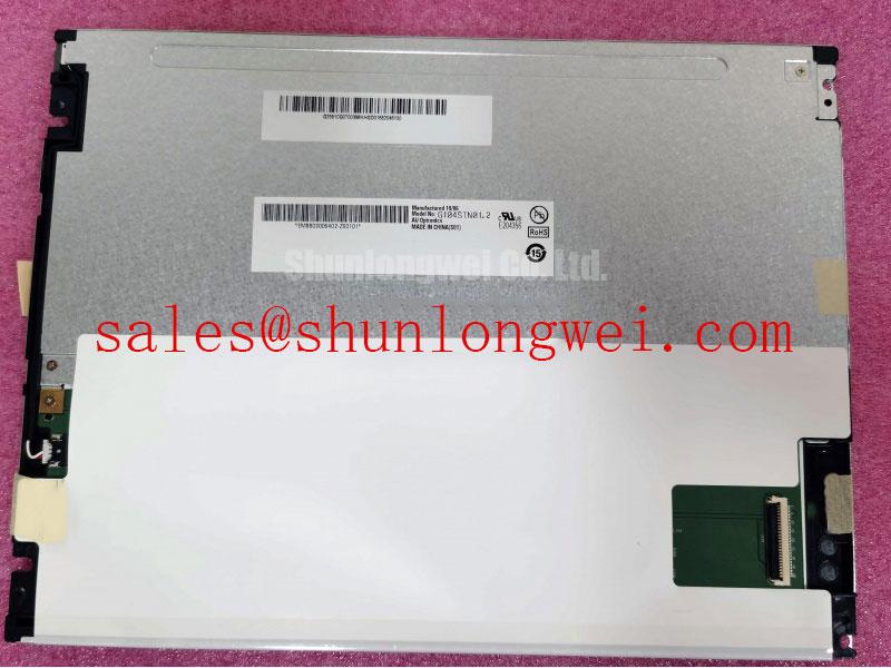
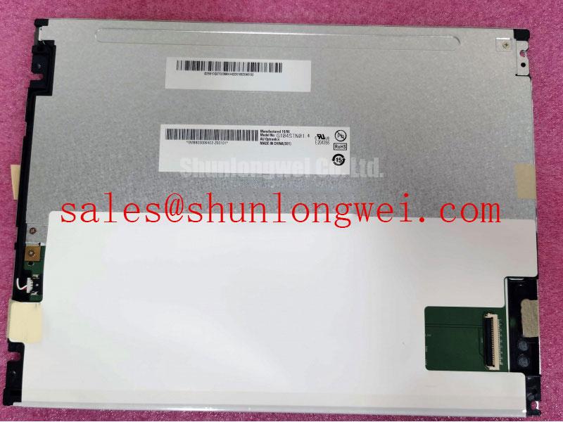
G104STN01-4 Identification Before Service
Check the label on the removed display and photograph its connectors before disconnecting the G104STN01-4. A matching model number is the first identification check, but the repair decision also depends on the host electronics, mounting arrangement and surrounding enclosure.
The G104STN01-4 is an AUO industrial-grade TFT-LCD display module (Official Factory Specification). The supplied factory identification does not establish its supply voltage, resolution, interface pinout, backlight drive requirements or operating temperature limits. Obtain the original panel documentation and the equipment wiring record before applying power or ordering a replacement assembly.
Backlight Driver Verification, Dimming and Flicker Control
Start at the backlight connection, not at the brightness setting on the operator screen. Record the connector orientation and trace its cable to the installed driver. The supplied G104STN01-4 identification does not confirm a WLED arrangement, a constant-current input, a PWM dimming ratio or a backlight lifetime rating. Those details must come from the original panel documentation and the driver schematic; a display that fits the opening is not, by that fact alone, electrically compatible.
As a Design Consideration, separate a backlight fault from a video-path fault before replacing the panel. If an image appears faintly under external illumination while the backlight is dark, check the driver supply, enable signal, cable seating and brightness command against a known-good signal path. If illumination is present but unstable, capture the driver command and output with suitable instruments. Flicker can involve the command source, wiring or driver as well as the display, so a visual symptom should not be assigned to one cause without measurements.
Dimming behaviour matters during a repair because the machine controller may command brightness changes independently of image data. Verify the expected dimming method from the original equipment records, then observe whether illumination responds consistently through the range the equipment actually uses. Do not transfer a PWM setting or driver from another panel on the assumption that the two assemblies share a backlight specification.
Cold operation warrants a separate image check. Liquid-crystal transitions can slow as temperature falls (Design Consideration), making moving graphics look different from a room-temperature bench test. Compare the display at the equipment’s documented temperature limits and distinguish slower image transitions from unstable illumination. If the enclosure has a heater or temperature-control circuit, confirm its operation against the equipment design rather than assuming the G104STN01-4 requires one.
Where a second panel is being evaluated, G104VN01 V1 provides a separate model for a documented comparison. Check each panel’s drawing, electrical interface, backlight requirements and optical specifications individually; the model names do not establish interchangeability.
Mechanical Stress and Image-Defect Inspection
Inspect the display while it is supported in the intended mounting position. A picture that looks uniform on the bench can change after the bezel, gasket and chassis are assembled. Before tightening hardware, check that the module sits flat, cables clear the chassis and no gasket section is folded beneath a corner. The mounting drawing, rather than pressure on the visible glass, should determine where the assembly is supported.
A practical image check begins with full-field red, green and blue test images from a verified video source. Look for persistent lines, missing colour regions and changes that appear as the enclosure is assembled. Follow with dark and mid-grey fields to inspect uneven illumination and pressure-sensitive patches. Photograph defects with the test image, brightness command and mounting state recorded; these details make a later bench comparison useful.
With the display powered as specified by the equipment procedure, oblique flashlight inspection can help locate surface marks and regions that differ from the surrounding image. It cannot, by itself, establish a fracture in an internal driver connection. A fixed line could involve panel circuitry, a cable, a connector or the source signal. Recheck the cable and compare a known-good input before assigning the defect to the module.
As a Design Consideration, distinguish a dark backlight region from a missing image region by changing the displayed test colour and viewing under controlled ambient light. Check whether the defect follows image content or remains in the same physical area. General diagnostic distinctions between illumination, pixel response and signal faults are covered in The Ultimate Guide to Industrial TFT LCD Technology; the G104STN01-4 repair still requires measurements against its own documentation.
No backlight decay curve or service-life figure is established by the supplied factory identification. For maintenance planning, record measured brightness under repeatable conditions and compare it with the equipment’s acceptance criteria. That observation is more useful than assigning an unsupported lifetime to an individual module.
Edge Heat Flow, Enclosure Sealing and Cold Starts
Inspect the enclosure around the G104STN01-4 before attributing an optical defect to the panel. Dust at a gasket joint, a blocked ventilation path or a displaced seal can change the environment around the display. Check the gasket’s contact path with the bezel drawing and look for gaps or compression that varies around the opening. A separate cover lens or optical bond should only be treated as part of this assembly if the equipment build record confirms it.
Heat-spreader rails or other chassis features should be evaluated as parts of the host equipment, not presumed to be AUO requirements for this model. As a Design Consideration, keep intended heat paths unobstructed and assess whether nearby electronics create local heating, then verify panel and enclosure temperatures under the equipment’s operating conditions. Avoid placing a thermal interface against an unapproved display surface: pressure and heat-transfer changes need assessment against the mechanical drawing.
After a cold soak, watch the complete image as the equipment reaches its normal operating state. Delayed pixel transitions, temporary fogging on an external cover and a persistent backlight fault call for different checks. If moisture is visible, establish which surface carries it before opening the display assembly. Review enclosure sealing, drainage and temperature-control provisions against the machine design; neither airtight optical bonding nor a particular low-temperature rating is confirmed for the G104STN01-4 here.
For a heavy mining shovel or earthmoving-equipment telematics display, these checks are compatibility considerations, not an assertion that the module was specified for that vehicle. The integrator should verify the equipment’s vibration mounting, enclosure protection, temperature range, viewing requirements and electrical interface against the original panel documentation. Viewing-angle technology and colour behaviour should likewise be confirmed from that documentation rather than inferred from the industrial-grade designation.
Chassis Fastener Loading and Display Timing Checks
Set the module into the chassis without using fasteners to pull a misaligned bezel into place. Confirm that mounting points meet the drawing, the gasket contacts evenly and cable routing does not lift an edge. Tighten progressively in the pattern specified by the equipment manufacturer, then repeat the dark-field and mid-grey image checks. If a patch changes with assembly pressure, document the change and inspect the seating before treating it as a panel defect.
The supplied G104STN01-4 identification does not specify an M3 fastener torque or an allowable bezel compression. Fastener size and torque must be taken from the applicable panel drawing and host assembly procedure. Maintenance Note: Disconnect equipment power before reseating the display cable, and inspect gasket seating during scheduled enclosure checks.
If the panel powers up white, shows unstable colours or retains an image during shutdown, compare the observed power sequence with the original equipment and panel timing documents. As a Design Consideration, the video source, panel supply and backlight command should follow the documented sequence so that an apparent display fault is not actually a startup or shutdown mismatch. Check supply behaviour at the connector under load and inspect the cable before replacing the module.
The same documentation must establish the G104STN01-4 signal interface and its timing limits. Do not assume a TTL or LVDS connection from the cable’s appearance. Where the documented interface permits it, compare transmitted clock and data at appropriate test points with the equipment specification, including behaviour across its specified temperature range. The integrator should verify supply voltage, pin assignment, timing, mounting fit and backlight drive together before returning the display assembly to service.