

Content last revised on October 10, 2026
Wide Temperature Operational Margin and Sub-Zero Liquid Crystal Response
Inspect the bezel contact points and perimeter gasket before energizing a G104V1-T01 display assembly showing edge shadows or uneven brightness; enclosure pressure can change the observed defect without identifying an electrical failure. Photograph the unpowered installation, then compare the displayed image before and after releasing enclosure preload under controlled service conditions.
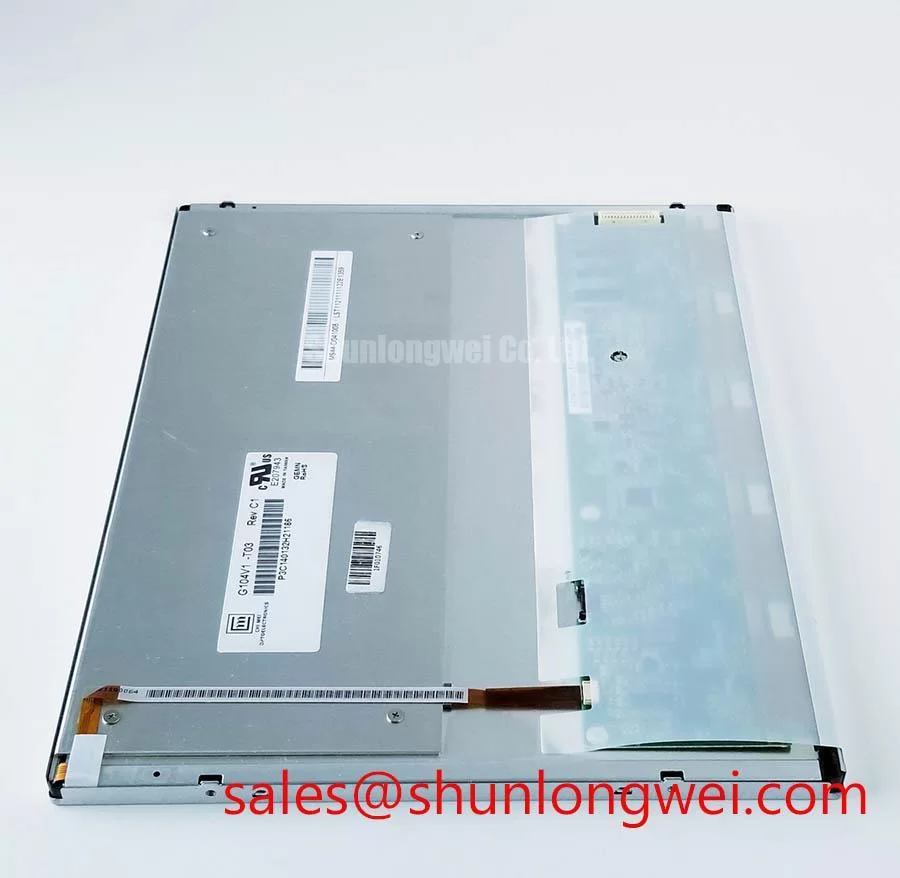
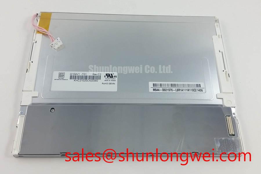
The G104V1-T01 product reference identifies a Chi Mei Optoelectronics (CMO) LCD panel with a TFT-LCD active matrix color display module format. Specification checkpoint: supply voltage, interface pinout, outline dimensions, optical ratings, operating temperature, backlight construction, and mounting limits require the applicable manufacturer datasheet. These values determine replacement compatibility; the model designation alone does not establish them.
Compare moving grayscale patterns at stabilized enclosure temperatures rather than judging cold performance from a stationary startup logo. As a Design Consideration, liquid crystal response generally slows as temperature falls, so moving text can develop trailing edges while a static image remains readable. Record panel-area temperature, image behavior, and warm-up progression together to separate temperature-dependent response from intermittent signal faults.
A slower grayscale transition is not automatically a failed panel. Check whether the effect changes consistently with temperature and whether the same video source produces stable results on a known-good assembly. Gray-to-gray response is transition-dependent; one visual observation cannot establish a response-time rating. Qualification should use the host equipment’s actual image patterns and acceptance criteria.
Inspect accessible perimeter areas for contamination, damaged sealing surfaces, and changes in gasket contact after thermal exposure. This is an Engineering Recommendation for the assembled enclosure, not a claim about the G104V1-T01’s internal sealant composition. During movement from cold storage into warmer humid air, allow the assembly to stabilize and check for condensation before applying power.
Evaluate backlight brightness separately from liquid crystal response. Compare luminance at consistent drive settings and stabilized temperature, while checking the host driver’s current regulation where applicable. Brightness depreciation, service life, and mean time between failures describe different quantities; a brightness-retention endpoint must not be treated as an MTBF rating. Establish inspection intervals from equipment duty, measured performance, and documented manufacturer limits rather than an assumed lifetime figure.
Polarizer Durability and Optical Film Inspection under Direct Industrial Lighting
Display a grayscale ramp under the actual overhead lighting and examine it from the intended operator position. As a Design Consideration, reflected light can wash out dark tones even when the display produces an acceptable image in a dim workshop. Separate front-surface reflection from viewing-angle effects by changing the light position while keeping the observer’s position fixed, then reversing that procedure.
Inspect the exposed surface for scratches, cleaning residue, and uneven reflections without applying pressure. Anti-glare and anti-reflection treatments perform different optical functions, and neither treatment should be assigned to this model without its optical specification. Viewing-angle behavior also depends on panel technology and test criteria; symmetrical viewing cones or a particular liquid crystal mode cannot be inferred from the TFT-LCD designation.
The explanation of optical diffusers and their role in light distribution provides useful background for understanding illumination uniformity. It does not identify the optical films inside this module. Keep service inspection external: opening the optical stack introduces contamination and disturbs alignment.
For replacement assessment, the NL6448BC33-24 is a separate candidate to investigate, not an established interchangeable substitute. Use the following comparison checkpoint before ordering or adapting a harness.
| Selection checkpoint | G104V1-T01 | NL6448BC33-24 |
|---|---|---|
| Product identity | CMO TFT-LCD active matrix color display module | Separate LCD candidate requiring independent qualification |
| Resolution and active area | Consult Datasheet | Consult Datasheet |
| Outline and mounting geometry | Consult Datasheet | Consult Datasheet |
| Supply, interface, and connector mapping | Consult Datasheet | Consult Datasheet |
| Optical and temperature limits | Consult Datasheet | Consult Datasheet |
When evaluating integration into a surgical navigation or ultrasound diagnostic display, designers should verify grayscale presentation, viewing geometry, and equipment-level requirements; the panel identity alone does not establish medical suitability.
Full-Screen Primary Color AOI Screening: Stuck Sub-Pixels and Background Uniformity
Run full-screen red, green, and blue patterns in sequence, recording the location and repeatability of any persistent sub-pixel anomalies. Follow with white, gray, and black backgrounds to distinguish isolated points from broad brightness gradients. Keep source timing, brightness settings, viewing position, and camera exposure consistent so that an apparent change is not introduced by the test setup.
As an Engineering Recommendation, compare images with the bezel fitted and with its preload safely released. A pressure-sensitive dark patch warrants mechanical investigation, but does not prove a particular internal failure. A persistent line should prompt checks of the signal path, connector seating, and repeatability with a known-good source before assigning the defect to internal driver circuitry.
For a dark screen, use oblique external illumination to check whether a faint image remains visible. That observation helps distinguish absent illumination from absent image formation, but is not conclusive by itself. Examine the host backlight circuit’s enable signal, supply behavior, and documented fault output alongside the visual test.
Where the installed driver provides open-load or short-circuit protection, interpret its shutdown and restart behavior against that driver’s documentation. Do not repeatedly force operation into a fault. If dimming is controlled by PWM, assess flicker, audible noise, and brightness progression across the equipment’s commanded range; switching frequency and acceptable behavior belong to the validated host design. The Industrial Display & HMI Solutions reference supports broader enclosure and interface troubleshooting.
Chassis Fastener Torque Sizing to Control Optical Mura Defects
Seat the display against its intended support surfaces before tightening the chassis fasteners, checking that the gasket has not folded or displaced. As a Design Consideration, uneven support and concentrated bezel pressure can alter image uniformity. Fastener size, tightening torque, thread engagement, and gasket compression must follow the approved assembly drawing rather than a generic screw-size rule.
Bring the enclosure together progressively, using a balanced tightening sequence where the mounting layout permits. Inspect dark and mid-gray backgrounds during assembly to identify changes associated with fastening. If a patch appears as a particular fixing is tightened, inspect support alignment and local interference instead of compensating by tightening adjacent screws further.
Check cable routing and connector clearance before closing the housing. A trapped harness can load the display frame or prevent the bezel from seating evenly. A touch overlay is a separate subsystem: glove response and wet-surface behavior require testing with the installed controller and cover construction, not assumptions about the LCD module.
Maintenance Note: Periodically inspect enclosure airflow paths and perimeter gasket condition without pressing on the display surface.
After reassembly, repeat the same image checks following temperature stabilization. If the equipment uses external heating, verify its control and temperature distribution as part of the enclosure qualification. Close the service task only after the assembled unit maintains acceptable image uniformity, connector retention, and gasket contact under its documented operating conditions.