





Content last revised on September 10, 2026
Polarizer Durability and Optical Film Inspection under Direct Industrial Lighting
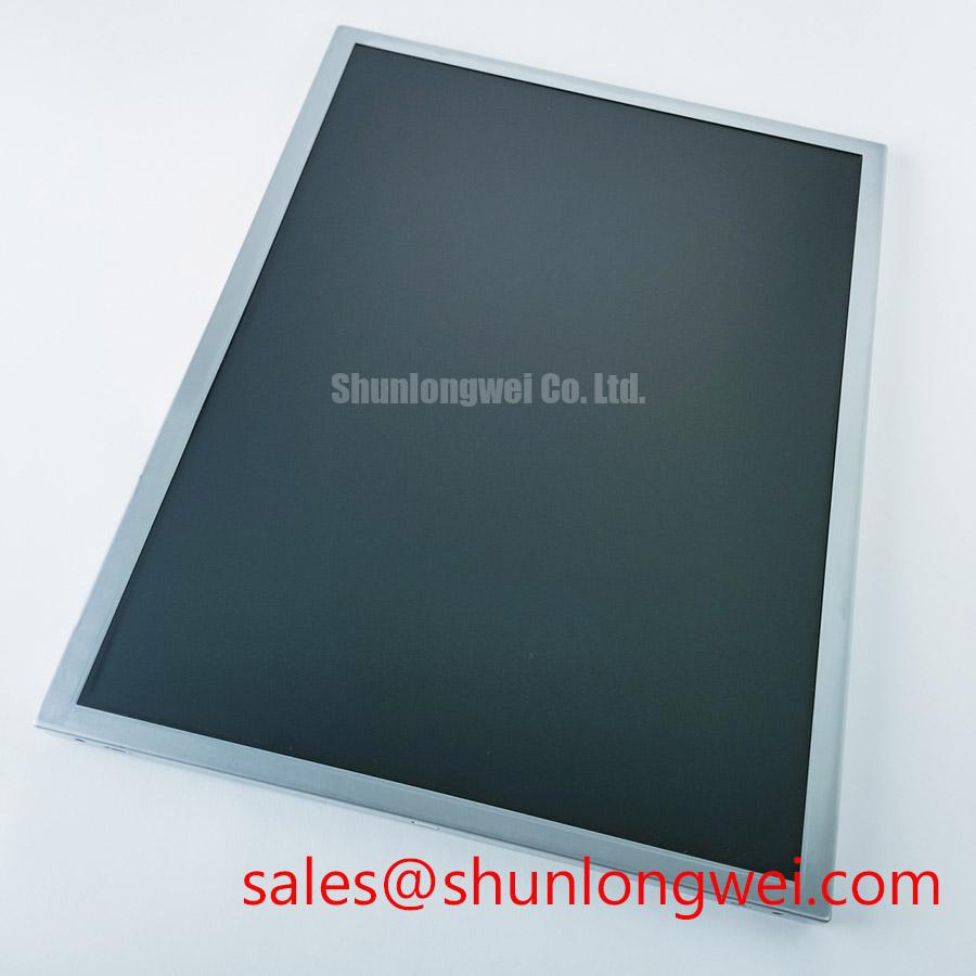
Inspect the polarizer surface of the G150X1-L03 at several viewing angles for scratches, pressure marks, coating irregularity, and localized reflections before connecting the panel to the target equipment. Then illuminate the connected panel with a uniform test image to evaluate visible optical defects. This first inspection is especially useful for a replacement LCD intended for a high-voltage substation protection or SCADA dispatch console, where overhead lighting, cabinet lamps, and daylight entering the control room can expose surface defects that are less visible on a dark bench.
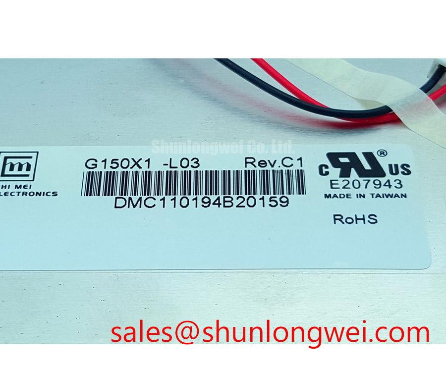
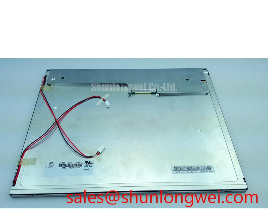
The confirmed product identity is an AUO TFT-LCD Active Matrix Color Display Module in the industrial LCD/HMI panel category. The supplied factory information does not establish a specific viewing-mode designation, optical retardation-film construction, surface coating type, luminance rating, contrast ratio, resolution, or viewing-angle specification. Those values should not be substituted with assumptions from another AUO panel. When the original system documentation identifies the required optical characteristics, compare the replacement against that record and against a known-good display.
A practical incoming inspection uses a white field, a black field, primary-color fields, and a mid-gray field. White helps reveal uneven illumination and contamination. Black makes bright leakage and corner nonuniformity easier to see. Red, green, and blue fields can expose pixel defects or color-channel abnormalities, while mid-gray is useful for identifying tonal nonuniformity and viewing-angle behavior. Observe the image from the normal operator position first, then move laterally and vertically without applying pressure to the panel.
TN grayscale inversion, IPS viewing symmetry, and MVA optical behavior are different panel characteristics and should not be inferred from the model number alone. If the host console requires stable alarm colors or readable trend graphics across several operator positions, verify the actual viewing performance of the installed unit under the intended room lighting. A broad viewing cone can improve shared-screen visibility, but it does not by itself prove that grayscale, color, or contrast remains uniform at every angle.
Anti-glare and anti-reflection performance also need separate evaluation. An anti-glare surface can reduce mirror-like reflections from ceiling lights, yet surface texture may alter perceived sharpness in small text. An anti-reflection treatment may preserve image clarity while still allowing strong directional reflections from a nearby lamp. Test the panel with the same font size, alarm colors, and screen background used by the SCADA interface rather than relying on a generic photographic image.
Cold-environment testing deserves particular attention when the display cabinet is installed near an unheated equipment room or exposed to low ambient temperatures. Liquid-crystal response can change as temperature falls, so a moving alarm banner or rapidly changing measurement may appear slower than it does at room temperature. This is a system-level behavior to measure on the actual panel and controller combination. If the equipment requires cold start operation, designers should verify warm-up behavior, image stability, and any heater-strip control against the original equipment requirements.
Digital RGB Bus Synchronization and Logic Rail Verification
Probe the panel supply and display timing at the connector during power-up, then compare the observed waveform and synchronization relationship with the known-good unit before investigating image artifacts. Split-screen images, unstable color planes, missing rows, or an image that appears offset can involve timing configuration, data mapping, connector contact, grounding, or a mismatch between the host controller and the panel interface.
The available factory data confirms the display category and TFT active-matrix construction, but it does not provide a confirmed logic voltage, TTL pin assignment, pixel clock limit, horizontal timing, vertical timing, 24-bit mapping, or power sequencing specification for this model. The system integrator should verify the required supply voltage and interface definition from the original panel documentation. Do not configure the replacement around an assumed 3.3 V or 5.0 V rail, and do not assume JEIDA or VESA mapping without checking the source documentation.
For a TTL RGB connection, inspect every signal group at the panel connector rather than checking only the clock. Red, green, and blue data bits should be traced from the controller to the corresponding panel pins, with enable and synchronization signals checked for correct polarity and timing. A single swapped bit can create color errors that resemble a defective LCD. A mapping error affecting a larger data group can produce severe tonal changes or an apparently divided image.
Use a short, well-referenced measurement connection when viewing the clock and data waveforms. Long ground leads can add ringing that is not present at the panel connector. In a factory environment with servo drives, switching supplies, and contactors, compare the display behavior with the machine idle and with the major electrical loads operating. If the symptom changes with motor or relay activity, inspect cable routing, return-current paths, shield termination, and cabinet bonding as part of the system diagnosis.
A 100-ohm differential routing rule is relevant to differential interfaces, but it must not be applied as a substitute for the confirmed interface type of this LCD. TTL RGB signals are generally evaluated as referenced single-ended logic, while LVDS uses differential transmission. If the host system uses an intermediate converter or a separate differential link, the board designer should control the intended characteristic impedance and pair matching according to that link’s documentation. Signal skew, edge rate, and connector discontinuity should be verified with suitable probing rather than corrected by changing panel settings at random.
Power-on behavior should be measured at the panel connector with the controller disconnected when safe to do so, followed by a controlled test with the display attached. Record the supply rise, enable transitions, clock start, and first valid frame. The requested timing window in a system design should come from the original panel specification or controller requirements, not from a generic LCD rule. When a blank screen occurs, separate a missing backlight from missing image data by checking the panel’s optical output and the electrical activity at the interface.
💡 Bench Tip: Use ESD protection and keep the flex or board-to-board connector perfectly parallel during insertion, then lock it without lateral force.
For a broader explanation of panel timing, optical behavior, and interface selection, engineers can consult The Ultimate Guide to Industrial TFT LCD Technology while keeping the G150X1-L03 connection decision tied to the original equipment records.
Flush-Mount Open-Frame Bezel Integration and Perimeter Gasket Shock Isolation
Check the metalwork opening against the replacement panel without tightening the fasteners, then inspect the perimeter for contact points, uneven gaps, cable pinch locations, and bezel pressure before applying power. An open-frame LCD can be electrically sound and still develop optical nonuniformity if the chassis presses unevenly against the display assembly.
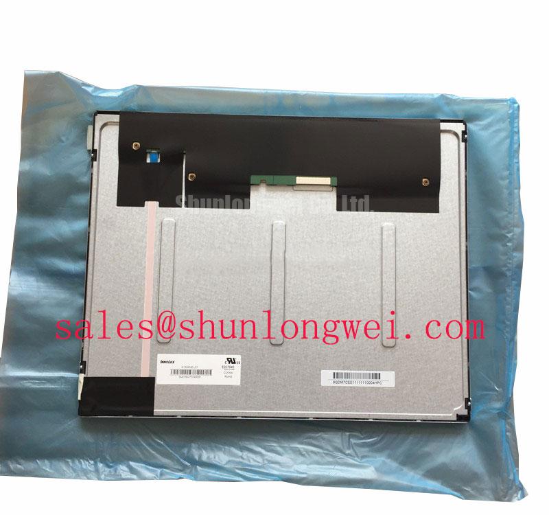
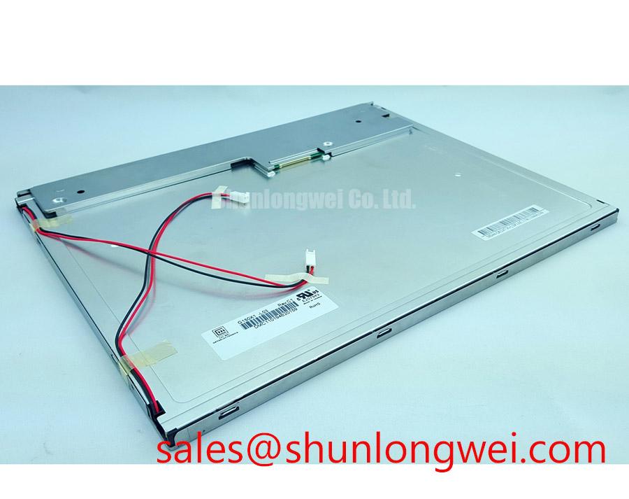
The confirmed physical description for the G150X1-L03 is a TFT-LCD active-matrix color display module. No factory outer dimensions, active-area measurements, mounting-hole pattern, bezel envelope, fastener specification, or gasket compression limit has been supplied here. The mechanical drawing for the original panel should therefore control the cutout, mounting references, connector clearance, and service access. Measure the actual panel and enclosure rather than scaling a photograph or using a dimension from a similar 15-inch display.
Use a flat support surface during fit-up and tighten mounting points progressively in a cross pattern. The purpose is to distribute mechanical load and avoid bending the frame. Fastener torque is a Design Consideration determined by the enclosure material, screw size, thread engagement, washer arrangement, and panel frame construction. Unless the AUO mechanical drawing gives a specific value, the equipment builder should establish the torque through a controlled fit test that confirms secure retention without bezel distortion.
A perimeter gasket can help isolate vibration and prevent hard contact between the enclosure and the display frame, but its material, thickness, compression, and environmental suitability must be selected by the system designer. Do not allow the gasket to overlap the active area, connector, venting path, or optical surface. After assembly, display a black and mid-gray field while viewing the panel in a darkened inspection area; localized bright or dark patches that change after loosening the bezel may indicate mechanical loading or assembly stress and require physical inspection.
For control-panel installations, evaluate the complete front surface under the actual lighting direction. Reflections from a flush bezel, protective window, or touch overlay can change perceived contrast even when the LCD itself is operating correctly. If a resistive or capacitive touch layer is being added, confirm its electrical interface, controller compatibility, glove response, water tolerance, and optical stack separately. The provided factory information identifies the LCD module, not a confirmed touch function or touch-panel specification.
Backlight control must also remain tied to the confirmed panel interface. If the host uses PWM dimming, the system designer should verify the accepted frequency range, duty-cycle behavior, enable polarity, and brightness response from the panel and backlight documentation. A generic PWM setting may create visible flicker, beat effects with cameras, or acoustic interaction in another part of the system. Check the result with the actual display content, especially thin text, alarm indicators, and slowly moving trend lines.
Shock and vibration testing should be performed after the bezel, gasket, cable restraints, and rear support are installed exactly as they will be in service. Monitor for intermittent image loss while gently applying the permitted enclosure-level vibration profile. If the picture changes, inspect connector retention and cable strain before attributing the symptom to the LCD cell. This approach keeps mechanical, electrical, and display causes separate during troubleshooting.
Luminance Output Control and Backlight Reliability Verification
Measure the display’s visible output at startup and after thermal stabilization while showing a uniform white field, then scan the perimeter and corners for brightness imbalance or local hot spots. This test should be repeated with the cabinet closed, because airflow, nearby power electronics, and bezel construction can change the thermal conditions around the display.
The supplied factory information confirms the G150X1-L03 as an AUO industrial TFT-LCD active-matrix color display module, but it does not establish a backlight half-life, L70 or B50 value, luminance tolerance, chromaticity target, thermal resistance, or allowable operating temperature. Those reliability figures must come from the applicable AUO documentation or a traceable system qualification record. No operating-life estimate should be assigned from the model name alone.
When integrating the panel into a SCADA dispatch console, maintain a thermal path that does not obstruct the display assembly or concentrate heat at one edge. An aluminum spreader rail may be evaluated as part of the enclosure design when measurements show localized heating, but its dimensions, attachment method, and temperature limits are system-determined. Verify the effect with thermocouples or an equivalent approved method at the display frame, backlight region, and nearby electronics during the most demanding operating condition.
Brightness control should be calibrated using the complete panel and controller, not by changing only the nominal backlight command. Record the displayed luminance at selected control points and check whether small command changes produce stable, useful visual steps. The calibration target should reflect the room lighting and operator requirements. Excessive brightness can increase glare and thermal load, while insufficient brightness can reduce alarm readability under direct industrial lighting.
Color uniformity is best reviewed with white, gray, and color test fields at the normal viewing position. Photographing the screen can help document a service condition, but camera exposure and white balance are not substitutes for an optical measurement. If color drift appears after warm-up, correlate it with cabinet temperature, backlight control, supply stability, and the video source before replacing the display module.
Cold-start verification should include image response, brightness behavior, and controller timing at the lowest required ambient condition. Liquid-crystal response may lengthen in cold conditions, while the backlight and power circuitry can show their own startup characteristics. If a heater strip is part of the enclosure, its control strategy, sensor location, insulation, and safety limits must be validated by the system engineer. The G150X1-L03 factory data supplied here does not authorize a particular heater temperature, delay, or operating sequence.
For service acceptance, retain the incoming inspection image set, connector inspection notes, supply measurements, mechanical fit record, and optical readings with the equipment asset record. This creates a useful baseline for later troubleshooting without assigning an unsupported field failure rate or lifetime prediction to the AUO module.