Content last revised on September 26, 2026
Controlled 100-Ohm Differential Impedance Flex Routing to Suppress High-Frequency Jitter
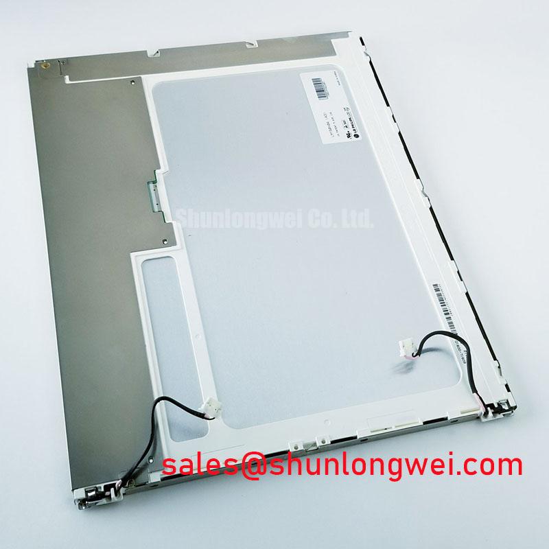
Before energizing a replacement panel, inspect the label, connector area, mounting frame, and visible glass edges, then compare the identification data with the original equipment documentation for LM150X04-TL01. This LG Display unit is identified here as an Industrial Grade LCD/HMI Panel in a TFT-LCD Display Module format. The supplied product record marks its factory specification status as verified, but it does not provide confirmed electrical interface, optical, touch, backlight, or dimensional values. Those items must be checked against the original panel documentation before installation.
For a panel used in an industrial HMI or a hazardous petrochemical Zone 2 explosion-proof operator station, the display module should be evaluated as one part of a certified enclosure and control system. The LCD itself must not be treated as independently certified for hazardous-area operation, EMC compliance, ingress protection, or explosion protection. Mechanical sealing, cable routing, thermal management, power conversion, and system certification remain the responsibility of the equipment integrator.
Begin the interface assessment by locating the original panel drawing or service manual and confirming the required logic supply voltage, connector pinout, signal assignment, and power sequencing. Do not assume that the replacement panel accepts a commonly used supply voltage simply because the connector appears mechanically compatible. The system integrator should verify the required supply voltage from the original panel documentation and measure the host board output during startup with the panel disconnected.
High-speed display links are sensitive to cable construction, return-path continuity, connector contact condition, and routing near switching power stages. A controlled differential routing structure may be appropriate for the host system, but a nominal impedance value is a Design Consideration rather than an LM150X04-TL01 factory specification unless it is explicitly stated in the applicable LG Display documentation. The same distinction applies to pair skew, rise time, and any proposed startup interval. Engineers should validate the complete host-panel channel with an oscilloscope and the original known-good assembly before changing the cable or controller.
JEIDA and VESA data mapping should also be confirmed from the source equipment documentation. Incorrect mapping can produce color inversion, unstable synchronization, split-screen behavior, missing columns, or an image that appears to respond normally while displaying incorrect tonal data. These symptoms should not be assigned to the LCD module alone without checking the controller configuration, connector orientation, cable continuity, and signal quality.
If the host uses PWM for backlight control, the driver frequency and duty-cycle behavior must be verified at the controller output. The required PWM range is system-dependent and is not a published factory parameter in the supplied product record. Designers should check whether the panel expects a brightness command, a direct enable signal, or a dedicated backlight interface. A bench test should compare minimum, nominal, and maximum brightness commands while monitoring flicker, audible noise, startup behavior, and thermal rise.
For a petrochemical operator station, keep display wiring physically separated from contactors, variable-frequency motor-drive conductors, and high-current DC conversion loops where the enclosure design permits. The purpose is to reduce coupled noise while preserving service access and the enclosure’s required sealing arrangement. If jitter appears only when adjacent equipment switches, compare the display signal at the source and at the panel connector before replacing the LCD.
Incoming Benchtop Inspection: COG and TAB Anisotropic Conductive Film Integrity
Incoming inspection should start with the module unpowered. Examine the glass perimeter, flexible cables, connector stiffeners, frame, and visible driver-bond areas under uniform light. Look for lifted edges, creasing, contamination, impact marks, or uneven mechanical pressure. A visual check cannot prove the condition of internal COG or TAB bonding, so it should be followed by a controlled functional test rather than a force or flex test.
Connect the panel using the approved cable orientation and a current-limited laboratory setup that matches the original system documentation. Apply the normal display test pattern and inspect red, green, blue, white, black, and mid-gray fields. This primary-color sequence can help separate color-data errors from illumination irregularities, but it does not provide a definitive root cause on its own. Record whether the defect remains fixed at one location, follows the signal source, changes with temperature, or varies when the cable is reseated.
A flashlight held at an oblique angle can assist with a dark-room inspection of the image. A 45-degree viewing angle is a practical Design Consideration for revealing faint edge shadows, uneven illumination, or areas where the image content is present but the backlight is not. This procedure is observational only. It should not be used to press the glass, flex the frame, or apply localized heat to the bonded regions.
When a line defect or partial image is observed, compare the same signal path with a known-good panel or test source. Check connector contacts, ground continuity, cable seating, controller mapping, and supply stability before attributing the issue to a bonded driver. Differential-pair impedance and skew targets belong to the system interconnect design and should be verified against the host controller requirements. They are not established LM150X04-TL01 specifications in the supplied factory data.
Surface treatment also deserves attention in an HMI replacement. The supplied product information does not confirm an anti-glare, anti-reflective, touch, or cover-glass option for this model. Do not advertise or design around AG or AR performance without a matching optical specification. In a high-brightness control room or outdoor-facing cabinet, evaluate reflections using the actual window, bezel, lighting angle, and operator viewing position. A clean, compatible front surface is often more important than a nominal brightness assumption.
Touch performance must be treated separately from the LCD image function. The supplied record does not confirm a resistive or capacitive touch layer. If the original station uses glove operation or wet-finger input, verify the complete touch assembly, controller, overlay, grounding method, and software calibration. The LCD module alone should not be presented as a guaranteed glove-touch or water-touch solution.
For additional background on display interfaces, optical integration, and common panel selection errors, engineers can consult The Ultimate Guide to Industrial TFT LCD Technology while keeping the final electrical decision tied to the original panel documentation.
Backlight Architecture and High-Voltage Safety Evaluation
Do not assume that this model uses a particular backlight technology. The supplied factory information identifies a TFT-LCD display module but does not confirm CCFL, LED, backlight input voltage, ignition voltage, current regulation, dimming method, or protection thresholds. Values sometimes associated with legacy CCFL systems, including high-voltage striking figures, must not be transferred to this model without a matching manufacturer specification.
First identify the backlight architecture from the original equipment wiring and the panel documentation. If a separate inverter is present, inspect its output cable, connector insulation, strain relief, and chassis clearance according to the applicable service procedure. If the system uses an LED driver, verify the driver’s required current-control method and fault reporting before connecting the replacement panel. The same connector position may serve different electrical functions across visually similar display assemblies.
Backlight faults should be approached as a circuit-level investigation. Confirm the host enable signal, driver input power, output behavior under load, connector continuity, and any open-load or short-load indication. A dark screen may also result from a missing video signal, incorrect sequencing, or a protective shutdown. Measuring a high-voltage inverter output requires equipment rated for that task and a procedure that addresses stored energy; a casual probe measurement can damage the instrument or expose personnel to hazardous voltage.
Cold-environment behavior should be evaluated with the complete enclosure and controller, not by assigning an unverified operating range to the LCD. Low temperature can alter liquid-crystal response, cable flexibility, adhesive stress, and condensation risk. A heater strip or enclosure warmer may be appropriate in some installations, but its control threshold, power, and placement are system decisions. Engineers should verify temperature limits from the original LG Display documentation and use controlled environmental testing where the application requires it.
Condensation deserves specific attention during startup after a cold soak. Allow the enclosure, panel, cable assemblies, and protective window to reach a controlled condition before applying power when moisture could be present. Check the cabinet pressure equalization, gasket compression, cable glands, and drain strategy. A display that functions correctly on a dry bench may behave differently when moisture forms across connectors or optical surfaces.
Claims such as a fixed half-life, a specific MTBF, or a guaranteed service duration require an authoritative manufacturer source and the exact operating conditions. No such life figure is included in the supplied LM150X04-TL01 product record, so service-life estimates should not be presented as a factory guarantee. Maintenance planning should instead use measured brightness, startup behavior, temperature history, and fault records from the installed system.
Radiated Emissions Evaluation and Backplate Grounding
Install the panel in its intended bezel or carrier before performing noise evaluation. The mechanical frame, shielded cable path, controller board, power converter, and cabinet bonding arrangement can all influence image stability. A backplate connection may reduce unwanted common-mode current, but the correct bonding method depends on the enclosure construction, protective-earth scheme, insulation requirements, and applicable system standard.
Do not state that LM150X04-TL01 independently complies with CISPR Class A or Class B. EMC classification applies to the tested equipment configuration, cable arrangement, operating mode, and installation conditions. A display module can contribute to emissions or susceptibility performance, but it cannot independently establish compliance for the finished operator station.
For a practical investigation, observe the panel while nearby variable-frequency drives, relays, and contactors operate through their normal switching states. If horizontal bands, pixel jitter, or intermittent synchronization appear, compare the symptom with the drive switching event and inspect the display cable route. Check connector shielding, return-path continuity, chassis contact, and the separation between display wiring and high-current conductors. A ferrite component may be useful in some assemblies, but its impedance profile, current rating, placement, and effect on signal integrity must be selected by system testing rather than assumed.
A 360-degree shield termination can be considered where the cable and enclosure design support it, but the method must not compromise creepage, clearance, serviceability, or the hazardous-area certification of the complete station. In a Zone 2 petrochemical application, the finished operator station requires assessment under the relevant equipment approval route. The LCD module should be treated as an internal component unless its own documentation explicitly states otherwise.
Image quality checks should include uniform white and gray fields, dark-field inspection, color transitions, and repeated power cycling under the intended controller settings. Record whether an artifact is fixed to the panel, moves with the cable, follows the image source, or disappears when the adjacent power converter is disabled. This evidence is more useful than assigning a single cause to a visual symptom.
⚠️ Maintenance Note: Inspect the cabinet cooling path, bezel sealing surfaces, cable strain relief, and gasket condition at scheduled service intervals, especially after repeated door opening or panel replacement.
Before releasing the assembly to service, confirm that the replacement identification matches the approved bill of materials, the connector orientation is correct, the host power sequence is documented, and the enclosure has passed its own functional, thermal, sealing, and EMC checks. The supplied product identity for LM150X04-TL01 is LG Display Industrial Grade LCD/HMI Panel with a TFT-LCD Display Module construction; all application-specific electrical and environmental limits should be verified from the original factory documentation.