
Content last revised on September 12, 2026
G170ETN01.0 AUO TFT LCD Module: Field Verification Before Integration
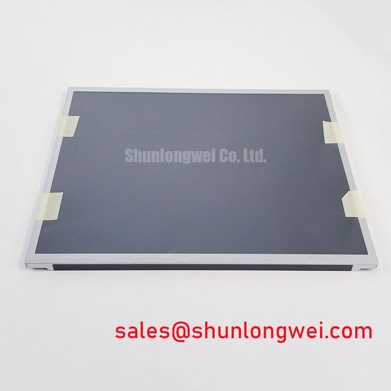
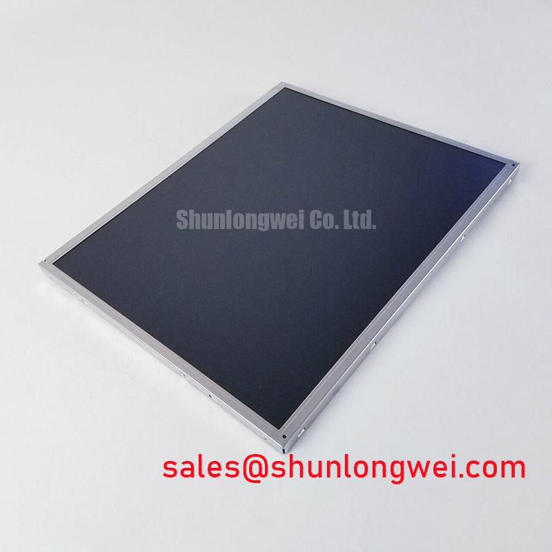
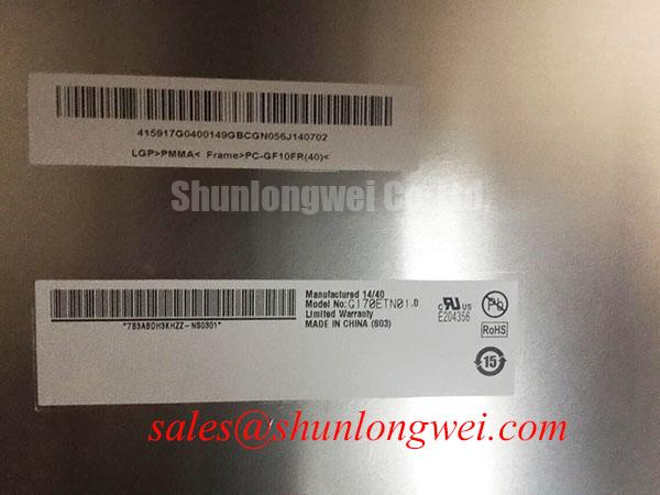
Verify the replacement panel against the original equipment documentation, inspect the display surface and frame for transport damage, and confirm the marking G170ETN01.0 before connecting power or signal cables. The unit is identified as an AUO industrial grade LCD/HMI panel in a TFT LCD display module format, with its product identity recorded for verification.
For repair engineers, the first compatibility check is physical rather than electrical. Compare the active display area, outer frame, mounting points, connector position, cable exit direction, bezel opening, and panel thickness with the failed unit. A matching diagonal size alone does not confirm mechanical interchangeability. The control board, cable path, backlight assembly, and enclosure may impose additional constraints that must be checked against the original panel documentation.
| Model | G170ETN01.0 |
| Manufacturer | AUO |
| Product category | Industrial Grade LCD/HMI Panel |
| Module format | TFT LCD Display Module |
| Specification status | Product identity recorded |
The information available for this product identifies the panel category and module construction but does not establish a complete electrical interface definition in the supplied factory data. The system integrator should verify the required logic supply, signal interface, connector pinout, pixel format, backlight type, and timing values from the original panel documentation before applying power.
For a same class sourcing comparison, engineers may also review M185XW01 VE as a separate reference model. It should not be treated as a direct replacement without confirming resolution, dimensions, connector assignment, timing, backlight requirements, and controller compatibility.
Managing Edge Temperature and Possible Optical Color Shift
When the panel is installed behind a restricted bezel, inspect the enclosure for uneven contact with heat producing components. Localized heating near the display edge can produce nonuniform optical conditions, but the supplied factory information for G170ETN01.0 does not specify an optical yellowing limit, LED L70 value, B50 value, internal light guide material, or approved heat spreader construction. These characteristics must not be inferred from the product name alone.
A practical design consideration is to keep heat sources, power conversion components, and high current conductors physically separated from the display perimeter where the mechanical layout allows. If an aluminum spreader or frame rail is considered, the system designer should evaluate whether it transfers heat into the panel rather than removing it. Thermal mapping during normal operation is more useful than assuming that a metal rail will improve display life.
For a panel used in a surgical navigation display or ultrasound diagnostic terminal, evaluate the complete optical stack after enclosure assembly. Check brightness uniformity, grayscale appearance, color temperature, and visible edge variation at the intended viewing angle. Any acceptance limit should come from the equipment manufacturer or system validation plan, not from an unverified assumption about this AUO module.
Sub zero operation also requires a system level review. Liquid crystal response can become slower as viscosity changes with temperature, yet the available product information does not provide a confirmed operating temperature range or gray to gray response specification for this model. Designers should verify the actual temperature rating and assess image response during controlled cold start testing. If a heater is used, its control method should prevent local hot spots and should be validated with the panel installed in its final enclosure.
The linked The Ultimate Guide to Industrial TFT LCD Technology provides broader background for evaluating panel interfaces, optical behavior, and industrial integration factors. It does not replace the original AUO documentation for model specific limits.
Logic Supply Sequencing and Display Data Compatibility
Before connecting the display to a controller, identify the exact logic voltage required by the original documentation. The supplied factory data does not confirm whether G170ETN01.0 uses a 3.3 V or 5.0 V logic rail, so the system integrator should verify the required supply voltage from the original panel documentation rather than selecting a value by similarity to another TFT module.
Use the original controller and cable as the known good reference whenever possible. Confirm connector keying, pin numbering, ground allocation, enable signals, clock polarity, data order, and timing parameters. LVDS and TTL interfaces are not interchangeable, and a connector with a similar physical form does not prove electrical compatibility. If the panel uses LVDS, the board designer should preserve controlled differential routing and minimize discontinuities through the connector and cable transition. The appropriate impedance, pair arrangement, and length relationship remain system design values that must be verified with the selected transceiver, PCB stackup, and cable assembly.
JEIDA and VESA data mapping should also be checked against the controller configuration. Incorrect mapping can produce wrong colors, unstable imagery, or split screen artifacts that may resemble a defective panel. During diagnosis, compare the clock and data activity with a known good display path and use an oscilloscope or suitable differential probe where the interface architecture permits. A symptom should not be assigned to a single cause without checking power integrity, grounding, cable orientation, controller settings, and timing together.
Power sequencing is another integration checkpoint. Confirm the relationship between logic power, display enable, reset, and backlight control from the source documentation. Avoid hot plugging the display cable during troubleshooting because an apparently harmless connection change can expose the interface to uncontrolled transient conditions.
💡 Pro Tip: Keep the high speed differential signal path away from switching power loops and verify pair symmetry at the connector transition to reduce the risk of clock related image instability.
Backlight control must be treated separately from the logic interface. The available specification context does not confirm the backlight technology, drive current, dimming method, PWM frequency, or duty cycle linearity for this model. The integrator should verify the original backlight driver requirements and then evaluate flicker, acoustic behavior, brightness uniformity, and thermal performance in the assembled product.
Backlight and Insulation Checks for Diagnostic Display Assemblies
Do not assume a high voltage CCFL interface or a constant current LED input from the model number. The supplied product data identifies G170ETN01.0 as a TFT LCD display module but does not confirm its backlight architecture. The original panel documentation must establish whether an external inverter, LED driver, enable line, analog dimming input, or PWM control is required.
If the service assembly uses a high voltage inverter, insulation testing belongs to the complete approved assembly and its safety procedure. The stated context does not provide a verified cold ignition voltage, transformer insulation rating, creepage requirement, clearance requirement, or dielectric withstand value for this AUO model. Engineers should therefore use the equipment manufacturer’s service limits and applicable laboratory procedures rather than applying an assumed 1500 Vrms or 1650 Vrms test level.
Where a constant current LED driver is used, verify the driver output range, current regulation behavior, enable polarity, open load response, and dimming compatibility. A nominal PWM ratio or claimed dimming depth cannot be assigned to this panel without a supporting factory specification. Check the assembled display for visible flicker through the intended camera system and for brightness changes caused by cable routing, grounding, or driver interaction.
For high precision surgical and ultrasound diagnostic display terminals, the display should be evaluated as part of the complete visual chain. Confirm grayscale rendering, image stability, backlight recovery after standby, connector retention, and enclosure clearance. Medical equipment suitability, EMC compliance, insulation reliability, and certification belong to the finished equipment and its certification file; this display module should not be represented as independently certified for the complete system.
During replacement work, record the original connector orientation and cable routing before removal. Compare the new panel at low risk bench conditions using the approved controller, then inspect the image while changing operating states such as startup, standby, backlight enable, and signal loss. If the result differs from the reference unit, isolate the observation by measuring the supply rails, checking the control sequence, and confirming the signal mapping instead of assuming a panel failure.
G170ETN01.0 is therefore best assessed through a documented mechanical, electrical, optical, and backlight compatibility review. The product identity is recorded as an AUO industrial grade LCD/HMI panel in TFT LCD display module form. All unlisted interface and environmental limits should be taken from the original factory documentation before a repair release or production integration decision.