Content last revised on October 18, 2026
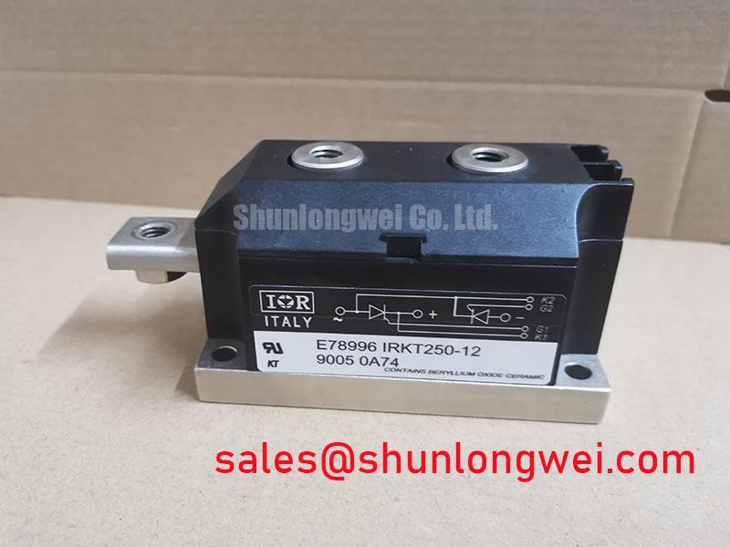
IRKT250-16 Operational Boundaries: Evaluating High-Frequency Switching Loss Dissipation Limits
I check the commutation method before assessing switching losses: a thyristor must recover its blocking capability after current extinction, rather than respond to an IGBT-style gate turn-off command. For the Vishay IRKT250-16, the specified 1600 V and current rating identify electrical boundaries; they do not establish a permissible high-frequency switching rate. Recovery conditions, conduction waveform, and heat removal determine the practical operating envelope.
Design Consideration: When examining commutation waveforms, distinguish diode reverse-recovery peak current and recovery time from thyristor turn-off time. A recovery-time figure alone does not establish soft recovery; the current decay shape and subsequent voltage ringing also matter. Capture device voltage and branch current together, using appropriately rated isolated measurement equipment, and relate the observed transition to the actual circuit path rather than assigning every current spike to the module.
At the thermal interface, inspect heatsink passages, fan operation, seating surfaces, and accessible thermal compound for deterioration during scheduled shutdowns. A temperature rise can reflect airflow restriction, connection resistance, or changing load conditions. Compare measurements at comparable loads before changing the maintenance interval. Treat this Power Block / Bridge Case as a mounted module, not as a press-pack assembly requiring an assumed spring preload or double-sided clamping procedure.
For replacement assessment, compare the terminal drawing, circuit arrangement, mounting dimensions, and rating conditions before considering another part. The UFB200FA40 is a separate comparison reference, not an established same-specification substitute. Matching a current figure or package appearance alone does not demonstrate interchangeability.
Field Diagnostics & Commissioning: RC Snubber Network Optimization to Prevent Problems in IRKT250-16 Topologies
Capture the voltage rise across the nonconducting branch and the gate-to-cathode waveform before changing an RC snubber. Design Consideration: Unwanted firing can involve excessive voltage rise, gate interference, or an inadequate commutation interval; distinguish these mechanisms by correlating the waveforms with the commanded firing instant. Keep probe connections from creating misleading ringing or an unintended ground path.
Snubber resistance and capacitance should be evaluated against the measured transient, repetitive dissipation, and discharge current at turn-on. Increasing capacitance can reduce voltage rise while increasing stored energy delivered during switching. A series reactor can limit current rise, but its saturation behavior and circuit interaction require system-level evaluation. Neither component should be assigned a numerical value solely from the module’s voltage and current ratings.
For gate wiring, verify the designated gate and cathode connections against the terminal drawing, and examine their routing relative to power conductors. An IGBT Miller-plateau tuning procedure is not an appropriate substitute for thyristor triggering analysis. Any gate suppression or bias arrangement should follow the actual driver circuit and permitted gate limits. Where the equipment schematic also identifies an IRKV300-04, assess its branch function and protection separately rather than assuming identical firing requirements.
The physical principles described in Transient-Voltage-Suppression (TVS) Diodes for Surge Protection help distinguish voltage clamping from RC damping. Similarly, Inductive Kickback Protection via Flyback Diodes in Relays explains inductive current continuity, but does not establish a suitable suppression circuit for this power module. Protection selection depends on the actual energy source and current path.
Benchtop Waveform Tuning: Mitigating Stress via Sinusoidal 10ms Half-Cycle Surge Current Limits on IRKT250-16
Compare the prospective fault-current waveform with the manufacturer’s surge conditions before selecting a semiconductor fuse. Design Consideration: A sinusoidal 10 ms half-cycle is a surge-test condition, not a repetitive operating allowance. Initial junction temperature, pulse duration, and reverse-voltage reapplication conditions belong with any I_TSM assessment; the continuous current rating cannot replace them.
Use the device’s surge and I²t data alongside the fuse manufacturer’s coordination information. Compare total clearing behavior at the prospective fault current, including the applicable voltage and starting temperature. Do not treat a fuse’s nominal current or pre-arcing I²t alone as proof of semiconductor protection. Controlled commissioning should establish normal operation, not deliberately reproduce a destructive surge limit.
For a potential grid-tied static var compensator or thyristor-switched capacitor application, evaluate circuit arrangement, capacitor charging transients, and firing synchronization before accepting the module into the assembly. The discussion in Peak Efficiency in Solar and Energy Storage provides broader converter context for reviewing transient margins; it is not an IRKT250-16 qualification standard.
Maintenance Note: Trend terminal temperature rise under comparable load and verify clear airflow before attributing increased heating to the semiconductor.
During shutdown, inspect terminal joints and restore fastening only to the applicable manufacturer torque specification with a calibrated tool. Check thermal-interface condition when temperature trends or service access justify inspection, rather than assigning an unsupported replacement interval. After cold storage or a humid shutdown, address condensation before energization and confirm that enclosure ventilation has not introduced moisture at the terminals.