
Content last revised on November 13, 2026
Preventing Spurious Faults: IEC 61000-4-5 Industrial Surge Immunity Guidelines for UFB200FA40
Isolate the power assembly, discharge stored energy, and trace the main-terminal connections before disconnecting the UFB200FA40 during a fault investigation. Record the installed orientation and conductor positions so that the replacement assessment follows the actual circuit rather than the housing appearance. A resistance check across an assembled converter can include parallel paths through snubbers and other semiconductors; isolate those paths before interpreting the measurement.
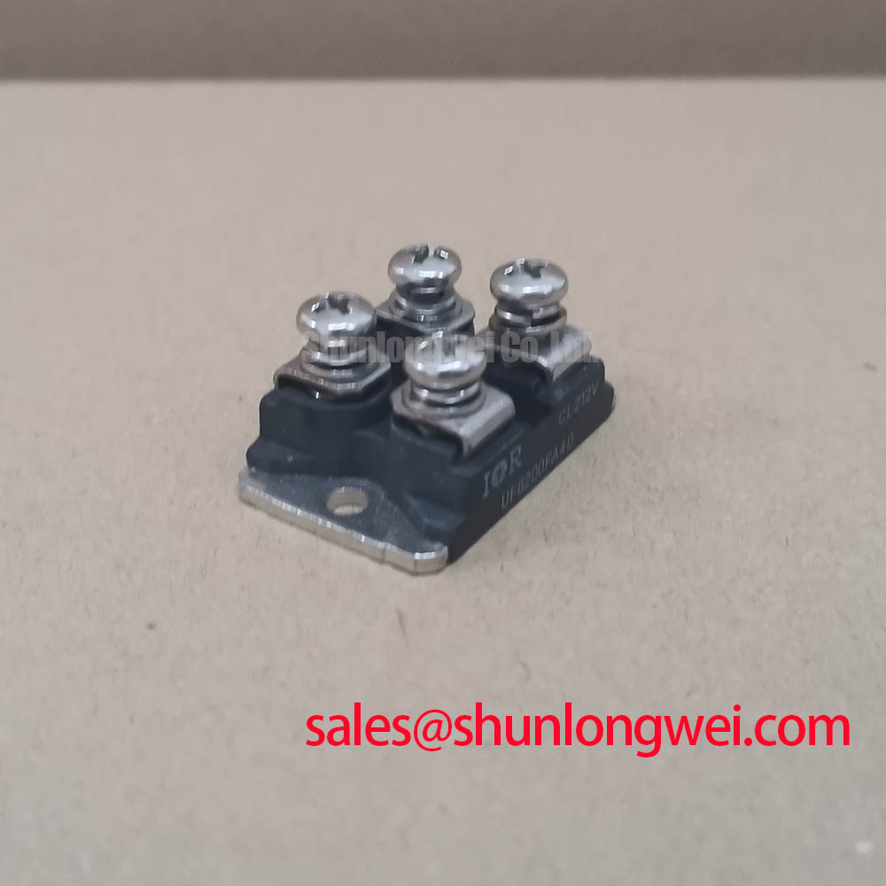
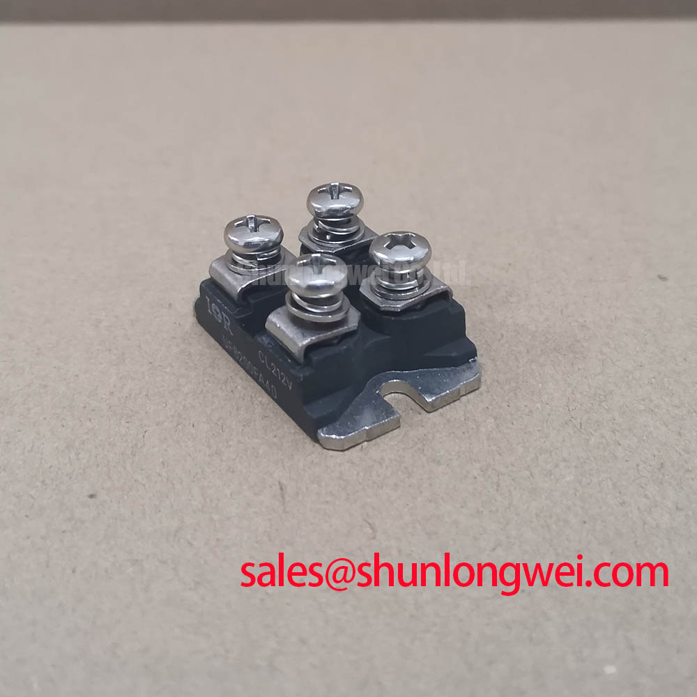
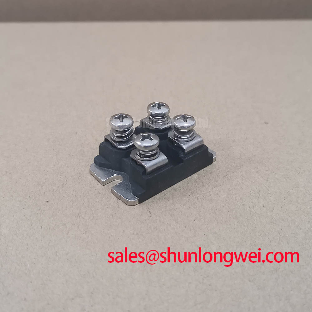
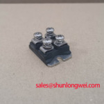
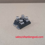
The Vishay UFB200FA40 is an ultrafast rectifier diode module with a 400 V repetitive peak reverse-voltage rating and a 200 A average forward-current rating under the specified datasheet conditions, in a SOT-227 package. It is not a thyristor module and has no firing gate. Consult the datasheet for current-rating conditions, internal connections, surge withstand, thermal limits, and tightening torques. The voltage rating is a device limit, not a recommended system operating voltage.
Trace the AC input protection from the incoming terminals through the surge suppressors, semiconductor fuses, and local suppression network. The applicable surge-immunity reference is IEC 61000-4-5, not IEEE 61000-4-5. It addresses equipment-level testing and does not establish an independent immunity certification for this module.
Design Consideration: coordinate an MOV against the maximum sustained supply voltage, its clamping characteristic under the relevant surge waveform, and the semiconductor blocking limit. Include conductor inductance between the suppressor and protected terminals when evaluating the residual transient. A suppressor positioned at the cabinet entrance does not necessarily control the waveform at a remotely connected power module.
An RC snubber should be assessed against the actual commutation waveform, repetitive energy dissipation, and component pulse capability. During troubleshooting, inspect its connections and measure the voltage directly across the relevant power terminals using appropriately rated instrumentation. Excessive voltage slew and peak overshoot are separate observations; neither identifies a failed module without supporting measurements.
For fuse coordination, compare the fuse total clearing I²t with the semiconductor withstand data under compatible voltage, temperature, and fault conditions. Pre-arcing I²t alone does not describe the complete interruption event. Record the selected fuse and its coordination basis in the repair documentation rather than treating a matching current marking as proof of protection.
The Mitsubishi Electric Diode Modules Lineup provides a useful industry reference for distinguishing diode-module families; it does not establish UFB200FA40 ratings or interchangeability.
UFB200FA40 Operational Boundaries: Evaluating Diode Commutation and Reverse Recovery
Establish the internal circuit and terminal functions before connecting test equipment. Confirm diode polarity and terminal assignments from the datasheet rather than from terminal position or resemblance to another module. Do not connect firing equipment to this diode module.
Design Consideration: assess reverse-recovery behavior under the actual forward current, current fall rate, reverse voltage, and junction temperature. Recovery characteristics depend on these conditions; a quoted recovery time alone does not establish switching loss or suitability for every converter. Include the interaction with the commutating switch and the power-loop inductance when evaluating voltage overshoot.
During evaluation, correlate diode current with the voltage across the diode. This helps distinguish reverse-recovery current, commutation behavior, and circuit ringing without imposing a single-cause diagnosis. Use appropriately rated probes and account for measurement-loop inductance when interpreting fast transients.
For adjacent IGBT switching stages, The Art of Balancing IGBT Switching Speed and Stability offers context on gate-loop damping and switching behavior. The IGBT gate drive can affect diode commutation, but its gate-drive guidance is not a UFB200FA40 specification.
Practical tip: Keep the power commutation loop compact to limit inductive overshoot, then verify the resulting terminal-voltage peaks during controlled switching tests.
UFB200FA40 Operational Boundaries: Evaluating Junction-to-Heatsink Heat Dissipation Limits
Inspect the heatsink contact surface for contamination, raised edges, and evidence of uneven seating before mounting the module. Design Consideration: apply the specified thermal interface material and follow the documented tightening sequence so that contact pressure develops without distorting the housing. Terminal tightening and base mounting serve different mechanical functions and should not share an assumed torque value.
Separate junction-to-case thermal resistance from the case-to-heatsink interface contribution. For pulsed loading, evaluate transient thermal impedance against pulse duration, repetition, and initial temperature rather than relying solely on steady-state thermal resistance. Case-temperature measurements support this assessment but do not directly measure the instantaneous junction-temperature peak.
When evaluating compatibility with a converter assembly, compare the circuit topology, blocking requirements, repetitive current waveform, reverse-recovery behavior, cooling arrangement, and terminal clearances. A related power module such as the VSKDS201/045 should not be treated as a verified direct replacement without matching device type, internal circuit, and electrical and mechanical requirements.
Before re-energizing, check that conductor routing does not load the terminals mechanically or reduce the assembly’s required creepage and clearance. Refit barriers and confirm unobstructed cooling paths. Under controlled loading, record case temperature, heatsink temperature, and operating waveform together so that the repair acceptance decision reflects the installed thermal interface and actual electrical duty.