Content last revised on October 10, 2026
FRS200AA40 Circuit Protection & Reliability: Evaluating Post-Surge Reverse Voltage
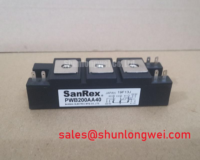
Isolate the power stage, discharge the DC link, and record the terminal condition before evaluating a failed FRS200AA40 in a thyristor-switched capacitor or grid-tied SVC cabinet. Check for heat discoloration, loose power connections, and abnormal mechanical loading before applying any reverse voltage. The supplied factory specification identifies this SanRex (Sansha Electric) power module with a 200.0 A rated current, a Standard Industrial Rating for working voltage, and a SanRex Power Module package.
For a replacement assessment, match the original circuit position, semiconductor polarity, terminal arrangement, cooling method, and protective coordination. The current rating is an official specification, but it should not be treated as a complete operating limit until the switching duty, junction temperature, fault current, and cooling conditions have been checked in the equipment.
Post-surge inspection should begin with the protection record rather than an immediate power-up. In a thyristor-controlled capacitor branch, a high-current event can leave the module electrically stressed even when the housing appears intact. Review the semiconductor fuse selection, its published clearing characteristics, and the circuit’s measured prospective fault current. The relevant fuse coordination must compare the fuse clearing energy with the thyristor or diode withstand data for the actual installation.
The sinusoidal ten-millisecond half-cycle surge rating, commonly identified as ITSM in semiconductor documentation, is a datasheet limit that must be read together with its test conditions. It is not a substitute for calculating the cabinet fault duty. Before reverse voltage is reapplied, confirm that the surge event did not exceed the available thermal and electrical margin, then inspect the gate and main terminals for looseness or heat movement.
Use the manufacturer’s mounting instructions for the specific hardware and heat-spreader arrangement. A flat, clean mating surface supports predictable thermal transfer, while uneven clamping can distort the module base or create local thermal resistance. Terminal lugs should be aligned without forcing the body of the module, and the final connection should be checked after the first controlled thermal cycle. Industry mounting torque values are design considerations, not confirmed factory parameters for this listing.
The Shindengen Power Semiconductor Modules & Diodes reference library is useful for reviewing general module protection terminology, while IEC 60747-2 provides a recognized framework for diode-related semiconductor measurements. These references support test planning; they do not add ratings to the FRS200AA40.
Assembly Integrity & Layout Architecture: Implementing Type-2 Coordination: Sub-Cycle Dead-Short for FRS200AA40
Dead-short coordination depends on the complete path from the supply bus through the semiconductor fuse, module terminals, busbar, and load connection. Selective protection should clear the fault before the semiconductor’s permitted surge and thermal limits are exceeded. The engineering record should therefore retain the fuse I2t clearing value, prospective current, conductor impedance, and the applicable thyristor or diode withstand data.
| Evaluation item | FRS200AA40 | Replacement review point |
|---|---|---|
| Manufacturer | SanRex (Sansha Electric) | Confirm the original manufacturer marking and circuit position |
| Rated current | 200.0 A | Compare with the equipment duty and thermal conditions |
| Working voltage | Standard Industrial Rating | Verify against the original system documentation |
| Package | SanRex Power Module | Match mounting, terminals, polarity, and cooling interface |
The same review should be applied before considering the related FRS200BA60 as a cross-reference. A similar physical appearance does not establish electrical interchangeability. Confirm voltage class, internal circuit arrangement, gate characteristics, surge capability, and terminal layout from the relevant product documentation before approving any substitution.
For the assembly itself, keep the high-current loop compact and mechanically supported, with adequate creepage and clearance for the cabinet’s insulation environment. Condensation, conductive dust, and damaged insulating barriers can reduce the effective insulation margin. In an SVC cabinet, the module should also be assessed alongside the upstream rectifier and charging network; the PDMB75E6 may be relevant as a separate complementary stage, but it is not an automatic replacement for this part.
⚠️ Maintenance Note: Inspect heat-sink cleanliness, thermal-interface material condition, terminal tightness, and contact temperature during scheduled preventive maintenance, especially where humidity or condensation is present.
Benchtop Waveform Tuning: Mitigating Stress via Gate Trigger Current Dynamics on FRS200AA40
Gate-drive evaluation should reproduce the installed trigger circuit, isolation arrangement, return path, and load conditions rather than relying on an unloaded pulse check. Confirm the gate pulse rise behavior, pulse width, pulse-current level, and repeat-pulse timing with a properly isolated measurement setup. Gate-drive conditions must be treated as application requirements to verify against the manufacturer’s gate data, not as independently confirmed FRS200AA40 ratings.
During bench work, observe whether firing remains consistent across the expected temperature range and current phase angle. A delayed or uneven trigger can increase conduction stress in a parallel path, while excessive gate-drive energy can overstress the gate circuit. The control designer should verify trigger amplitude, source impedance, isolation withstand, and return-current routing against the original gate requirements.
When reverse-recovery behavior from an associated diode affects EMI, evaluate the complete commutation loop with the intended snubber, wiring, and bus structure. A softer recovery profile can reduce ringing in some layouts, but the result depends on parasitic inductance, switching conditions, and control timing. The technical background in The 1200 V CoolSiC™ MOSFET Advantage in Three can assist broader power-conversion comparisons, but it does not define the ratings or gate behavior of this SanRex module.
For field acceptance, compare the repaired phase with a known-good phase using the same probe arrangement and operating point. Record gate waveform stability, terminal temperature trend, protective-fuse behavior, and capacitor-branch current before returning the cabinet to service. This approach keeps the 200.0 A official rating connected to real thermal and protection conditions without assigning unsupported surge, insulation, or lifetime values.