

Content last revised on September 26, 2026
KP800A1600V Gate Firing and Thermal-Electrical Limits
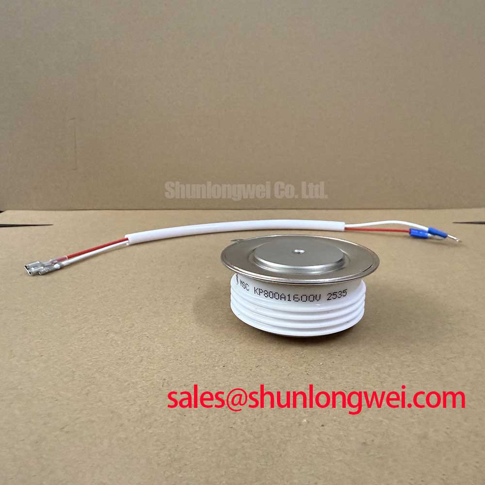
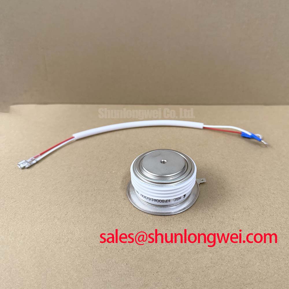
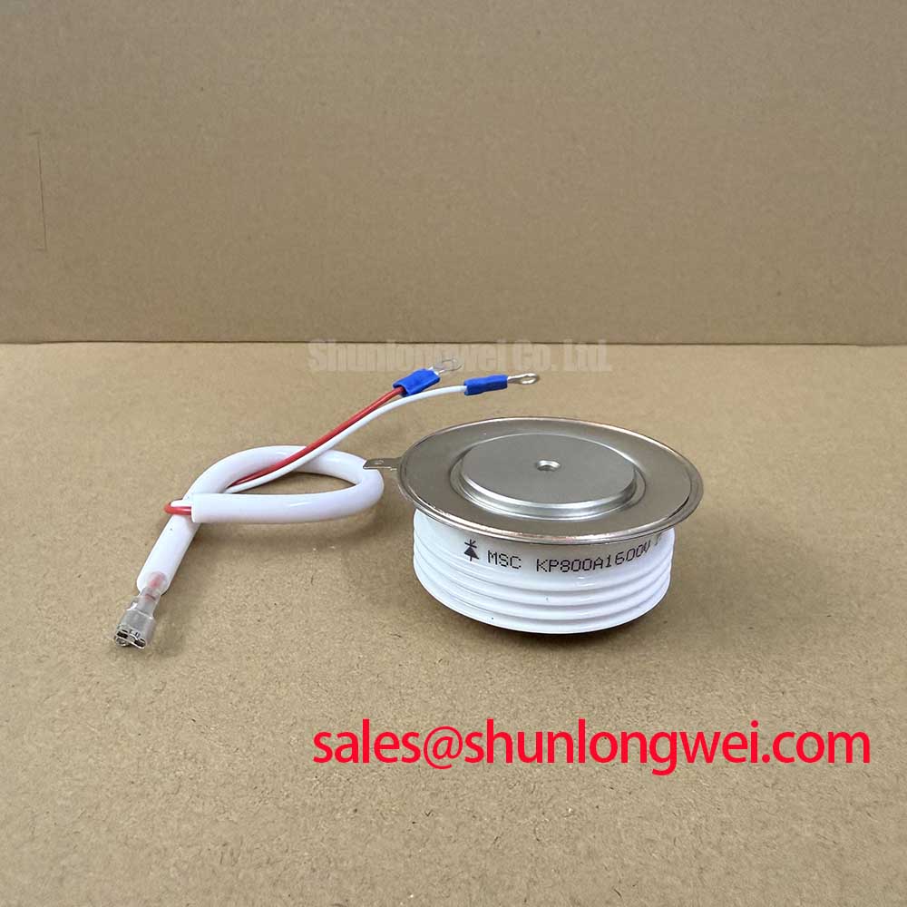
Before energizing a repaired rectifier, confirm the installed device marking is KP800A1600V, then compare its anode, cathode, and gate connections with the equipment schematic. A cold-state resistance check can help identify an obvious short, but it cannot establish the thyristor’s blocking capability or suitability under load. Record the existing heat-sink arrangement and fuse designation before disturbing either connection.
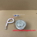
The KP800A1600V is a CRRC phase-control thyristor, or SCR. Its supplied official specifications state a 1600 V repetitive peak off-state and reverse voltage, a 800 A mean on-state current at a case temperature of 70°C, and a 1256 A RMS on-state current. These are distinct ratings: the mean-current figure is tied to its stated case-temperature condition, while the RMS figure does not by itself establish an acceptable operating point for a particular rectifier.
| Characteristic | Symbol | Official specification |
|---|---|---|
| Repetitive peak off-state and reverse voltage | VDRM / VRRM | 1600 V |
| Mean on-state current at Tc = 70°C | IT(AV) | 800 A |
| RMS on-state current | IT(RMS) | 1256 A |
| Peak surge current, 10 ms half-sine | ITSM | 10500 A |
| Maximum junction temperature | Tj(max) | 125°C |
| On-state voltage drop at peak | VTM | 1.80 V |
All values in the table are Official Specifications from the supplied factory parameters. The stated peak-voltage-drop figure is not a substitute for an on-state characteristic curve when estimating losses across the equipment’s complete current waveform.
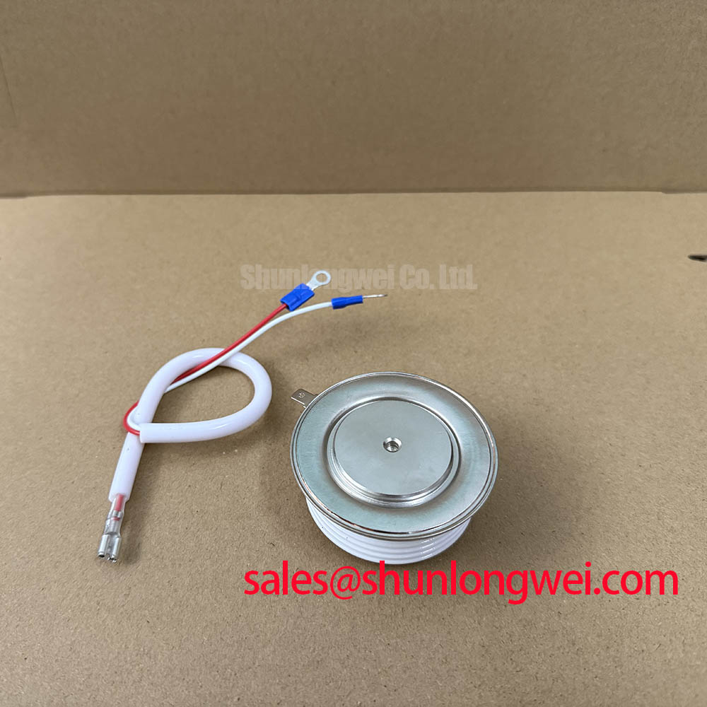
For gate commissioning, inspect the driver’s connection to the gate and cathode and compare the firing waveform with the original control specification. As a Design Consideration, a prompt initial gate-current rise and adequate gate drive during the intended firing interval help establish conduction across the device; insufficient drive deserves investigation when turn-on behavior is inconsistent. No gate-current rise rate, holding pulse level, or pulse-train timing is specified in the supplied parameters, so those settings must come from the original device documentation and measured circuit behavior, not from the main-current rating.
Where the controller uses repeated firing pulses, check their timing against the available anode voltage and phase-control sequence. A firing pulse that arrives outside the intended conduction interval may leave a healthy SCR apparently inactive. Conversely, a waveform seen at the driver output does not prove it reaches the device terminals: inspect the terminal connection and measure at an appropriate, safely isolated test point.
Benchtop Commutation Waveforms and Reverse-Recovery Questions
Capture anode-to-cathode voltage and load current during commutation, using probes and isolation practices suitable for the installed rectifier. A phase-control SCR does not turn off when its gate signal ends; it must experience the circuit conditions needed to cease conduction and recover blocking ability. Compare the observed waveform with the equipment’s expected phase sequence before attributing an abnormal turn-off trace to the thyristor.
The supplied KP800A1600V parameters do not state reverse-recovery peak current, recovery time, or a temperature coefficient for recovery charge. Those quantities should not be assigned values borrowed from a rectifier diode. As a Design Consideration, recovery behavior in the complete commutation path can affect voltage transients and conducted or radiated interference; measurements across relevant operating temperatures are more useful than an unsupported device-level prediction.
For a candidate green hydrogen electrolyzer DC power rectifier, designers should verify the actual bridge topology, cooling capacity, firing controls, and fault protection before assessing compatibility. If an associated stage uses a device such as the SKT340/18E, its ratings and function must be checked independently. The presence of both devices in a parts review does not establish that they belong in the same circuit.
When reviewing a replacement proposal, compare the original circuit requirements with the complete characteristics and mechanical documentation of each candidate. The TT570N16 is a separate device to evaluate, not a presumed drop-in substitute for the KP800A1600V. Voltage and current labels alone do not establish matching gate drive, terminal arrangement, thermal interface, or commutation performance.
Snubber, Reactor, and Fuse Coordination Around KP800A1600V
Trace the installed RC snubber from the schematic to its physical connections before changing components. As a Design Consideration, snubber resistance and capacitance are selected to manage the measured voltage-rise and transient behavior of the complete commutation loop. No permissible off-state voltage-rise rate or specified snubber values appear in the supplied device parameters. The system designer should therefore confirm the component ratings and waveform margins through tests under representative line and load conditions.
Apply the same distinction to a series saturable reactor. Its effect on turn-on current rise depends on the magnetic component, wiring, source impedance, and firing sequence; an SCR current rating does not determine reactor size. If a repair changes busbar routing or terminal placement, compare current-rise and peak-voltage traces with the documented configuration rather than assuming the original snubber and reactor remain appropriately coordinated.
💡 Pro Tip: Keep the commutation connections compact and symmetrical where the equipment layout permits, then verify peak-voltage margin with measured switching waveforms rather than relying on the nameplate voltage alone.
The official 10500 A peak surge-current rating applies to a 10 ms half-sine event. It is not a complete fuse-selection rule or a guarantee of survival in a sustained short circuit. For semiconductor fuse coordination, obtain the device’s applicable surge withstand and I²t information, the fuse manufacturer’s pre-arcing and total-clearing data, and the installation’s prospective fault-current profile. The supplied specifications do not include a device I²t coordination table, so no fuse size or short-circuit containment claim follows from them.
Junction-to-Heatsink Heat Removal and Mounting Checks
With the assembly isolated, inspect the mating surfaces, thermal-interface coverage, fasteners, and current-carrying terminals before reinstalling the device. Remove contamination that could prevent even contact, and follow the documented mounting sequence for the actual hardware. The supplied parameters identify a 125°C maximum junction temperature but provide no junction-to-case thermal resistance, mounting torque, baseplate material, or thermal-interface thickness; none should be assumed to be a factory requirement for this model.
As a Design Consideration, use an even thermal-interface layer and controlled contact pressure to reduce avoidable thermal resistance without distorting the assembly. Confirm torque from the applicable mechanical drawing or equipment service instructions. During a controlled load test, compare case-temperature measurements at consistent locations with the original equipment limits, while checking that the heat sink and airflow or liquid-cooling path operate as specified by the system designer.
If a temperature rise appears unexpected, work back through current distribution, firing symmetry, terminal resistance, and cooling contact rather than assigning a single cause from one reading. The Advanced Thermal Management Revolution provides broader context on heat-transfer interfaces; the mounting method and permissible temperatures for this SCR still require device-specific and equipment-specific verification.